
In this paper, we present a comprehensive analysis of the three-dimensional transient temperature field for spiral bevel gears operating under dry-friction conditions. Spiral bevel gears are pivotal components in high-performance transmission systems, such as those used in helicopters, where they endure extreme operational environments characterized by high speeds and heavy loads. The transition from starved lubrication to complete dry friction significantly exacerbates heat generation and accumulation, leading to rapid temperature rises. This thermal escalation can induce critical failure modes like surface pitting and scuffing, as well as cause thermal elastic deformations that may result in eliminated backlash or even system seizure, severely compromising the reliability and survivability of the transmission. Therefore, a detailed investigation into the temperature distribution of spiral bevel gears under dry-friction conditions is imperative for enhancing system durability and performance. Our work leverages finite element methods, incorporating principles from gear meshing theory, contact analysis, friction, and heat transfer to simulate and analyze the thermal behavior of these gears.
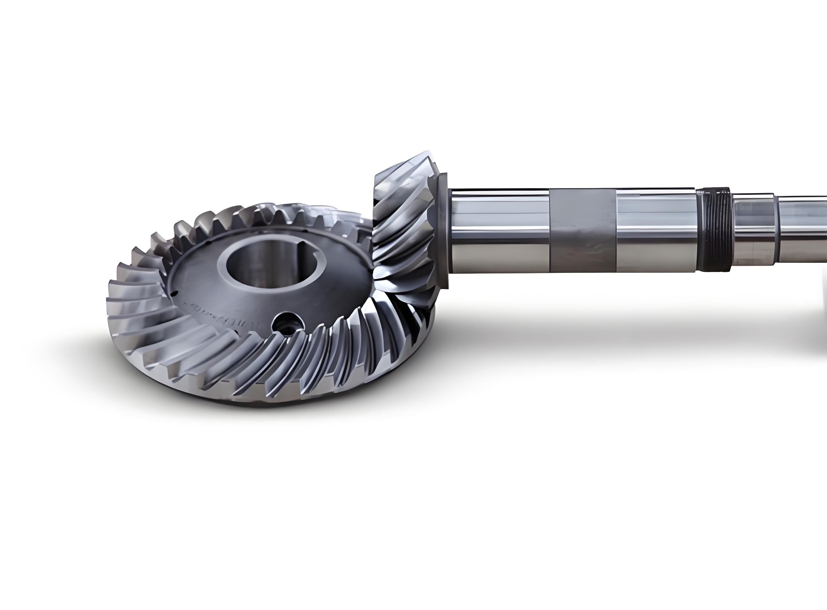
The modeling of spiral bevel gears begins with the acquisition of tooth surface data, which can be derived from gear generation equations, simulation programs, or coordinate measuring machines. For this study, we utilized a Fortran-based design program to compute the coordinate points on the tooth surface and root fillet. The process involved using the SGM program for cutter parameters and tooth cutting adjustments, followed by the Tooth Surface Equation program (TSF) to calculate equations for the tooth surface and root transition surface, yielding a grid of 17×12 coordinate points. The solid modeling adopted a bottom-up approach: discrete key points were created from the coordinate data, fitted into spline curves via programming, and then skinned into surfaces, which were finally enclosed to form solids. This methodology ensures an accurate geometric representation of spiral bevel gears, which is essential for subsequent finite element analysis. The complexity of spiral bevel gears necessitates simplifications to manage computational costs; thus, we reduced the full gear model to a single-tooth model. This simplification retains the critical thermal characteristics while significantly decreasing the number of elements and solution time. The material properties for the spiral bevel gears were defined as temperature-dependent, using tabular functions in ANSYS to fit curves for thermal conductivity, density, and specific heat capacity based on discrete temperature points. The finite element mesh was generated using the SOLID90 element, a 20-node hexahedral element well-suited for modeling curved boundaries and thermal analyses. The mesh for a single tooth is freely divided to capture the intricate geometry of spiral bevel gears effectively.
The thermal analysis of spiral bevel gears is governed by the three-dimensional transient heat conduction equation. Assuming the gear material is isotropic and devoid of internal heat sources, the equation is expressed as:
$$ \frac{\partial T}{\partial t} = \frac{k}{\rho c} \left( \frac{\partial^2 T}{\partial x^2} + \frac{\partial^2 T}{\partial y^2} + \frac{\partial^2 T}{\partial z^2} \right) $$
where \( T \) represents the temperature in °C, \( t \) is time in seconds, \( k \) is the thermal conductivity in W/(m·°C), \( \rho \) is the density in kg/m³, and \( c \) is the specific heat capacity in J/(kg·°C). To obtain a unique solution, initial and boundary conditions must be applied. The initial condition is derived from experimental data at the onset of dry-friction, given by:
$$ T(x, y, z, t) \big|_{t=0} = T_e $$
where \( T_e \) is the initial temperature. Boundary conditions are categorized into three types. For spiral bevel gears under dry-friction, the primary boundary condition is convection with the surrounding air, which falls under the third kind:
$$ -k \frac{\partial T}{\partial n} = h (T – T_f) $$
Here, \( h \) is the convective heat transfer coefficient in W/(m²·°C), \( T_f \) is the ambient air temperature, and \( \frac{\partial T}{\partial n} \) denotes the temperature gradient normal to the surface. Other surfaces may be treated as insulated or with specified heat fluxes, depending on the gear housing and operational context. The accurate determination of these conditions is crucial for realistic temperature field simulations of spiral bevel gears.
The heat load on spiral bevel gears originates predominantly from friction during meshing. The friction heat generated at the contact point is calculated as:
$$ Q = f \cdot V_s \cdot W $$
where \( f \) is the friction coefficient, \( V_s \) is the sliding velocity in m/s, and \( W \) is the normal load in N. Friction in gear contacts includes sliding friction, rolling friction, and internal friction due to elastic-plastic deformation; however, sliding friction is the dominant contributor and is thus the focus. To evaluate \( V_s \) and \( W \), we performed a loaded tooth contact analysis (LTCA) for the spiral bevel gears. This analysis determines the contact points, contact ellipse patterns, load distribution, and kinematic parameters along the path of contact. For computational efficiency, we selected 11 evenly spaced contact points along the contact path, covering the entire engagement region. The LTCA program, implemented in Fortran, outputs the sliding velocities and normal loads at these points, as summarized in the tables below. The friction coefficient for spiral bevel gears is sensitive to operational parameters and is estimated using an empirical formula:
$$ f = 0.002 \left( \frac{F_{tc}}{b \times 0.001} \right)^{0.2} \times \left( \frac{2}{\cos \alpha} \frac{(V_{1c} + V_{2c}) \mu_{ec} \times 0.001}{} \right)^{0.2} \eta^{-0.05 X_r} $$
where \( F_{tc} \) is the tangential load at the contact point, \( b \) is the face width, \( \alpha \) is the pressure angle, \( V_{1c} \) and \( V_{2c} \) are the velocities of the pinion and gear, \( \mu_{ec} \) is the dynamic viscosity of the lubricant (negligible in dry-friction but considered in transition), \( \eta \) is a viscosity factor, and \( X_r \) is the surface roughness factor. Under dry-friction conditions, the absence of lubricant alters the friction dynamics, necessifying adjustments based on material properties and surface conditions.
| Contact Point Number | Sliding Velocity \( V_s \) (mm/s) |
|---|---|
| 1 | 1000 |
| 2 | 2000 |
| 3 | 3000 |
| 4 | 4000 |
| 5 | 5000 |
| 6 | 6000 |
| 7 | 7000 |
| 8 | 8000 |
| 9 | 9000 |
| 10 | 9800 |
| 11 | 9500 |
| Contact Point Number | Normal Load \( W \) (N) |
|---|---|
| 1 | 6050 |
| 2 | 6100 |
| 3 | 6150 |
| 4 | 6200 |
| 5 | 6250 |
| 6 | 6300 |
| 7 | 6350 |
| 8 | 6400 |
| 9 | 6450 |
| 10 | 6500 |
| 11 | 6450 |
| Contact Point Number | Friction Coefficient \( f \) |
|---|---|
| 1 | 0.950 |
| 2 | 0.955 |
| 3 | 0.960 |
| 4 | 0.965 |
| 5 | 0.970 |
| 6 | 0.975 |
| 7 | 0.980 |
| 8 | 0.985 |
| 9 | 0.990 |
| 10 | 0.995 |
| 11 | 0.990 |
The total heat flux at each contact point is then computed using the formula for \( Q \), and these values serve as thermal loads in the finite element simulation. The distribution of heat flux across the contact points is critical for understanding the localized heating in spiral bevel gears. Additionally, the convective heat transfer coefficient \( h \) is a key parameter for dissipating heat to the environment. Under dry-friction, convection becomes the primary heat dissipation mechanism since lubricant flow is absent. The coefficient is derived from empirical correlations involving the Nusselt number \( Nu \), Grashof number \( Gr \), and Prandtl number \( Pr \):
$$ h = \frac{Nu \cdot \lambda}{l} $$
with
$$ Nu = C (Gr \cdot Pr)^n = C Ra^n $$
and
$$ Gr = \frac{\beta g (T_s – T_f) l^3}{\nu^2} $$
where \( \lambda \) is the thermal conductivity of air, \( l \) is the characteristic length of the gear tooth surface, \( C \) and \( n \) are constants dependent on geometry and flow regime, \( Ra \) is the Rayleigh number, \( \beta \) is the volumetric thermal expansion coefficient of air (approximated as \( 1/T_m \) with \( T_m \) as the mean temperature), \( g \) is gravitational acceleration, \( T_s \) is the surface temperature, and \( \nu \) is the kinematic viscosity of air. For spiral bevel gears, the tooth surfaces can be approximated as vertical plates or curved surfaces, and the constants are selected accordingly from heat transfer literature. Given that the temperature range for spiral bevel gears in dry-friction typically stays below 700°C, the Rayleigh number \( Ra \) is around \( 10^8 \), allowing the use of standard correlations. This dynamic calculation of \( h \) based on instantaneous surface temperature is implemented in ANSYS to enhance simulation accuracy.
We conducted the transient temperature field simulation using ANSYS 9.0, applying the aforementioned models and boundary conditions. The spiral bevel gear was analyzed under operational conditions with a gear speed of 10000 rpm and a pinion torque of 200 N·m. The initial temperature was set from experimental data, and the simulation tracked temperature evolution over time. The results reveal that the temperature on the tooth surface of spiral bevel gears rises rapidly during dry-friction, with distinct hotspots localized in the contact region. Two peak temperature zones emerge in the middle portion of the tooth surface, corresponding to the areas of maximum sliding friction and heat generation. The temperature distribution is non-uniform, with gradients extending from the surface into the gear body, influenced by the material’s thermal conductivity and the convective cooling on non-contact surfaces. The transient nature of the temperature field is evident from the time-dependent plots, showing a sawtooth-like increase in temperature due to the periodic meshing of spiral bevel gears. Over a span of 5 minutes, the maximum temperature increased by 22.5°C, underscoring the accelerated thermal accumulation in the absence of lubricant. This temperature rise can approach the scuffing threshold for gear materials, highlighting the vulnerability of spiral bevel gears under dry-friction conditions. The simulation also indicates that the root and non-contact regions experience lower temperatures, but thermal expansion from the hotspots can induce distortions that affect mesh alignment and load distribution.
| Time (s) | Maximum Temperature (°C) | Temperature Increase (°C) |
|---|---|---|
| 0 | 34.333 | 0.0 |
| 6 | 51.565 | 17.232 |
| 30 | 52.458 | 18.125 |
| 40 | 53.125 | 18.792 |
| 100 | 56.833 | 22.5 |
| 300 | 65.250 | 30.917 |
The analysis further demonstrates that the thermal behavior of spiral bevel gears is intricately linked to the sliding velocity, friction coefficient, and contact pressure distribution. These factors collectively dictate the heat flux input, and their optimization through tooth profile modifications—such as tip and root relief, crowning, or bias modifications—can mitigate temperature rises. For instance, reducing the friction coefficient via surface coatings or improved materials can directly lower heat generation. Similarly, enhancing the convective heat transfer through forced air cooling or gear housing designs can improve heat dissipation. The finite element model also allows for parametric studies to evaluate the impact of gear geometry, operating speeds, and loads on the temperature field of spiral bevel gears. Such studies are vital for designing spiral bevel gears that can withstand prolonged dry-friction periods, as required in emergency or high-performance scenarios. Compared to international benchmarks where spiral bevel gears have achieved up to 30 minutes of dry-friction operation, our simulations provide insights into the thermal limitations and potential improvements for domestic gear systems.
In conclusion, our study successfully simulates the three-dimensional transient temperature field of spiral bevel gears under dry-friction conditions using advanced finite element techniques. The model incorporates realistic boundary conditions, dynamic heat loads from loaded tooth contact analysis, and temperature-dependent material properties, ensuring high accuracy. The results confirm that spiral bevel gears experience rapid temperature increases in dry-friction, with hotspots in the contact area that can lead to thermal failures. To enhance the dry-friction capability of spiral bevel gears, we recommend optimizing tooth profiles to reduce friction coefficients, improving surface treatments to withstand high temperatures, and augmenting cooling mechanisms to dissipate heat more effectively. This work lays the foundation for further research into thermal deformation analysis and the development of specialized manufacturing processes for spiral bevel gears tailored to dry-friction environments. Future efforts could integrate thermal-structural coupling to predict deformations and stresses, or explore advanced materials with superior thermal properties for spiral bevel gears. Ultimately, understanding the transient temperature field is crucial for advancing the reliability and performance of spiral bevel gears in critical applications, ensuring their survivability under extreme conditions.