
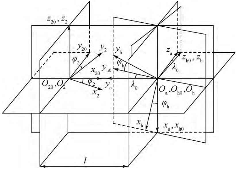
The coordinate system of face gear hobbing is established, as shown in Figure 7. The fixed coordinate system SH0 (xh0, yh0, zh0) is the initial position of hob; Sh (XH, YH, zh) is the motion coordinate system fixedly connected with the hob; SA (XA, ya, ZA) is an auxiliary coordinate system, which rotates around the XA axis λ The 0 angle is the SH0 coordinate system. During machining, the angle of face gear φ 2. Angle of and hob φ H satisfy the proportional relationship:
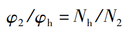
Where: for single head spherical hob, the number of hob heads NH = 1.
The transformation matrices are as follows:
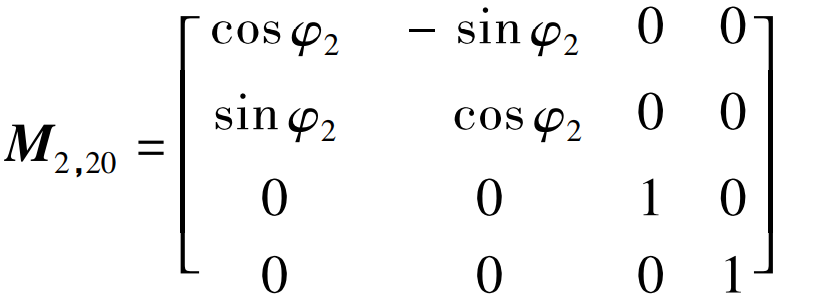
M2 and 20 are the conversion matrix from S20 to S2, and the expression is
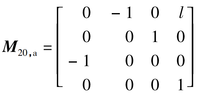
M20, a is the conversion matrix from Sa to S20, and the expression is
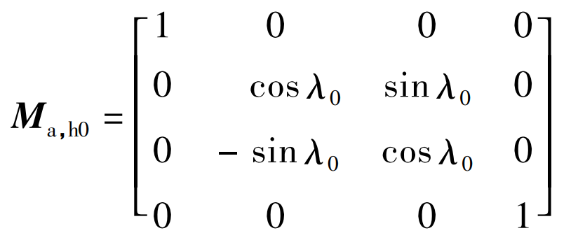
Ma, H0 is the conversion matrix from SH0 to SA, and the expression is
Mh0, h is the conversion matrix from sh to SH0, and the expression is

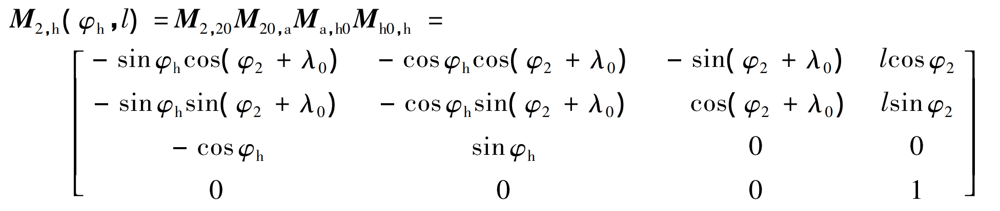
Then the conversion matrix from sh to S2 can be obtained as
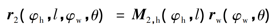
Then, the coordinate transformation equation of face gear tooth surface is
Like the gear shaper cutter machining face gear, the meshing equation of the spherical hob machining face gear can be obtained according to the meshing principle. Since the hob needs to feed along the face gear radial direction in addition to maintaining a constant transmission ratio with the face gear, the machining process is a two parameter envelope, that is, it should meet the following requirements at the same time:
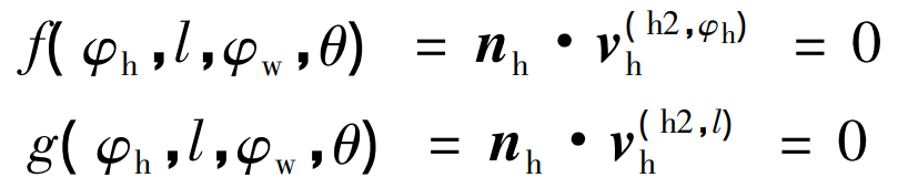
Where: the formula represents the relative rotational motion of hob and face gear, V (H2, φ h) H is when l is fixed φ H relative movement speed of hob and face gear during movement; The formula represents the radial feed movement of hob along face gear, V (H2, l) H is φ H relative movement speed of hob and face gear when it is fixed and l moves; NH is the normal vector of hob tooth surface.
The hobbing profile equation of face gear can be obtained by simultaneous formula.