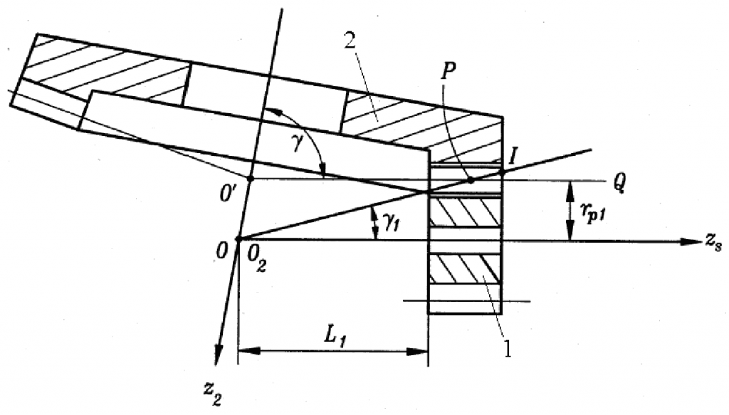
As shown in the figure, the intersection angle of the two axes is γ 1 is an involute cylindrical gear (pinion) and 2 is a bevel gear (face gear). When γ = At 90 °, all the teeth of the bevel gear are distributed on a circular plane and mesh with the cylindrical gear to achieve spatial intersection or interleaving. The bevel gear is called face gear, which is generally called face gear transmission. According to the different trend of face gear teeth, they can be divided into three types: straight teeth, helical teeth and arc teeth.
According to the theoretical knowledge of face gear, when the base circle radius of involute cylindrical gear is equal to the pitch cone radius of face gear, its meshing angle is 0 °. In fact, when the tool is cutting face gear, the conjugate tooth profile of face gear will be cut off by the tool tip transition part of the tool, resulting in undercutting of the tooth root part of face gear. The meshing angle is the pressure angle of the indexing circle at the radius of the indexing circle of the cylindrical gear and the pitch cone radius of the face gear. The farther away from the axis of the face gear, the larger the meshing angle of the face gear, and the smaller the tooth top thickness. Finally, the tooth top thickness of the face gear becomes 0, resulting in a sharp phenomenon in the tooth top part of the face gear. Because the face gear is prone to undercutting near the tooth root and sharpening near the tooth top, the tooth width and length of the face gear are limited and its bearing capacity is affected.
The application of face gear transmission in helicopter transmission system can not only reduce the weight of helicopter transmission system, but also improve the quality and reliability of helicopter transmission system. Compared with traditional bevel gear drive, face gear has simultaneous interpreting advantages.
(1) The axial error basically does not affect the transmission performance of face gear. For the transmission of a pair of bevel gears, the cone tops of the two bevel gears shall be ensured to coincide. If axial error occurs, serious eccentric load will be caused. Special anti dislocation design should be designed in aviation spiral bevel gear transmission, but it is not necessary to design anti dislocation in face gear transmission.
(2) The coincidence degree of face gear transmission is large. Under no-load condition, the coincidence degree of face gear can reach 1.6 ~ 1.8, and theoretically the coincidence degree can be more than 2.
(3) The transmission gear is an involute gear. According to the nature of the involute, the common normal of the meshing tooth pair does not change at each moment of meshing, which is very beneficial to power transmission.
(4) The theoretical transmission ratio is constant. The transmission ratio of the commonly used point contact bevel gear transmission will fluctuate. In principle, the constant transmission ratio transmission can not be guaranteed, while the face gear transmission has small vibration and low noise.
There are also some disadvantages in face gear transmission. Due to the particularity of face gear itself: the face gear is easy to produce undercutting in the tooth root part at the proximal end and sharpening at the tooth top part at the distal end. Therefore, under the condition of small transmission ratio, the tooth width of face gear is limited, which affects the bearing capacity of face gear. Due to the excellent performance of modern materials and the rapid development of modern design methods, the shortcomings of face gear are being gradually overcome, so that the limited tooth width of face gear can be effectively used. Unlike ordinary cylindrical gears, face gears have realized serialization. Due to their unique properties, the parameters of face gears may be certain parameters or limited groups of parameters in the design of face gears.

