
The correctness of the finite element model needs to be compared with the actual situation. If the simulation results are consistent with the actual production, it is proved that the established finite element model is correct. The model can be used for the next optimization design, which can guide the actual production. If the simulation results are quite different from the actual production results, it indicates that the established finite element model is problematic. The factors causing the difference mainly include the setting of boundary conditions, the selection of material parameters, the creation of geometric model, etc. the model should be modified on the premise of following the actual production.
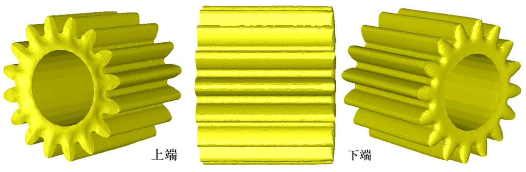
Figure 1 shows the numerical simulation results of spur gear under the original process, Compared with the actual production results (Fig. 2), the lower end face of the formed spur gear is convex, the lower tooth top is not fully filled, the tooth top collapse angle defect is obvious, the upper end face is concave, and the upper tooth top is not fully filled. Through visual comparison, the numerical simulation results are basically consistent with the actual production results, which preliminarily shows that the established finite element simulation is effective.

In order to further verify the accuracy of the finite element model, taking the simulation results and the actual production results as the measurement samples, the tooth top at the lower end of the spur cylindrical gear with serious angle collapse is selected for measurement. The physical measurement results are obtained by measuring the extruded spur gear with a coordinate measuring instrument, and the simulation measurement results are obtained by calculating the coordinates of the grid nodes on the tooth top. It can be seen that the maximum difference between the numerical simulation and the actual production results is 6.8%, and the error mainly comes from the material model and finite element mesh.
It can be seen that the simulation results are in good agreement with the actual production results. The established finite element model can be used to guide the actual production and can be used for further research and optimization. The simulation results can truly reflect the actual cold extrusion process and results.
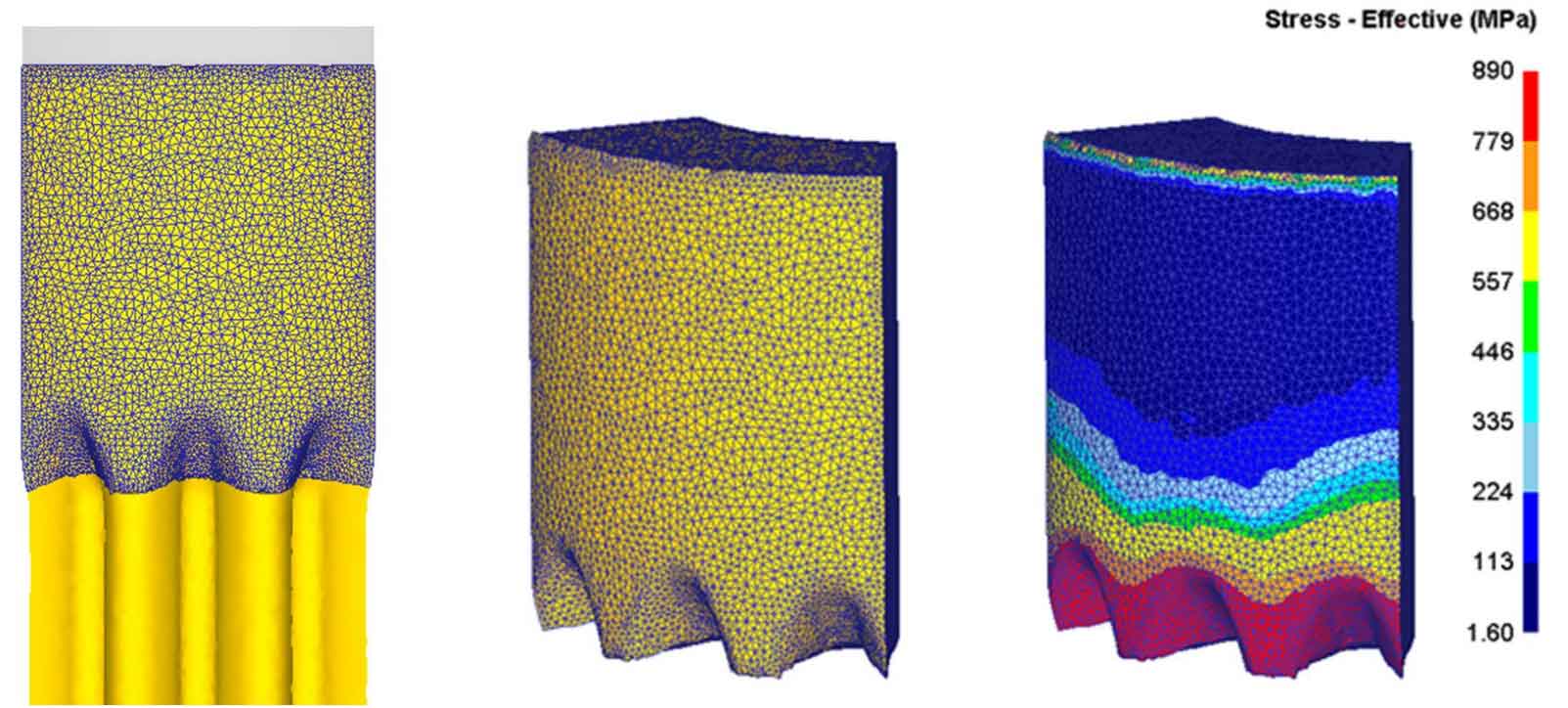
In order to explore the metal flow and stress-strain field distribution in the cold extrusion process of spur gear under the original process, the forming process is divided into three stages: initial stage, middle stage and final stage. In the initial stage of forming, the punch with mandrel moves down with the press and drives the blank gradually to the tooth shaped die. The blank is split by the tooth shaped die and enters the split extrusion area. This stage is divided into the initial stage of forming. At the initial stage of forming, the blank is gradually extruded into the tooth die and plastic deformation occurs, as shown in Fig. 3 (c); The part with large deformation is the tooth root part, as shown in Figure 3 (d). Although the original process adopts the “part pressing part” through forming, and the last extrusion part will provide a certain back pressure to the extrusion part formed by splitting extrusion, the back pressure is small. According to the minimum resistance theorem of metal flow, the axial flow of metal is easier than radial filling. At this time, the radial flow velocity of metal at the formed tooth top is negative, That is, the radial flow direction points to the axis, as shown in Figure 3 (E). The small back pressure during cold extrusion is the main reason for the insufficient filling of the top and bottom teeth and the collapse angle of the top teeth of the cold extrusion of spur gears.
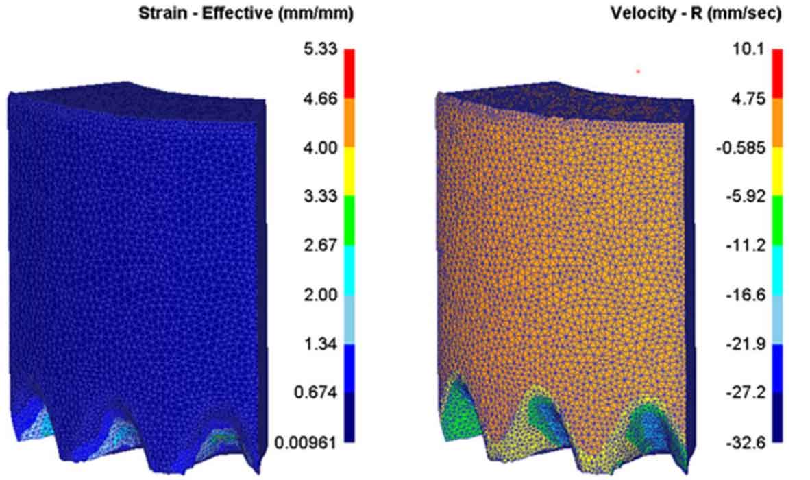
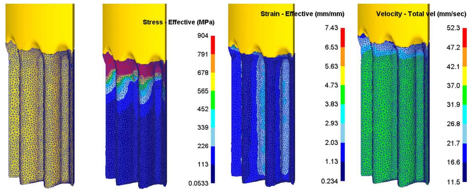
In the middle stage of forming, the split billet gradually enters the sizing zone. This stage is the stage of billet stable forming, and the extrusion force tends to be stable. In the middle stage of forming, the blank is gradually extruded into the tooth die and plastic deformation occurs. The deformation mainly occurs in the splitting extrusion area and sizing zone of the tooth die, as shown in Fig. 4 (b). The part with large deformation is still the root part, as shown in Fig. 4 (c). After the metal enters the sizing zone, the flow velocity tends to be consistent, and the flow direction is mainly axial flow, as shown in Fig. 4 (d).
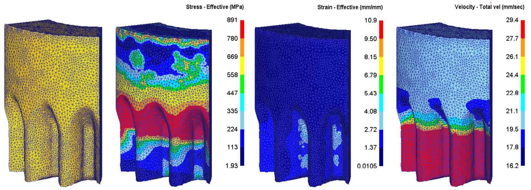
At the end of forming, the extrusion forming is basically completed, and the next one pushes the extrusion to continue to move downward. At this stage, the extrusion forming of a spur gear is basically completed. At the end of the forming stage, the tooth part immediately extruded and the next extrusion part are formed together. The deformation still mainly occurs in the splitting extrusion area and sizing belt area of the tooth die, and at this time, two parts are deformed, as shown in Fig. 5 (b). The part with large deformation is the tooth root part of the immediately extruded tooth part, as shown in Fig. 5 (c). At this stage, the metal flow is mainly axial flow with uniform velocity, and the metal belongs to rigid translation without deformation after passing through the sizing belt, as shown in Fig. 5 (d).
The cold extrusion forming process of spur gear is a complex process of metal flow and elastic-plastic deformation. The main factors leading to the low forming accuracy of spur gear are the elastic recovery of cold extrusion parts and die deformation, which are directly related to the metal flow, stress-strain and temperature in the forming process.