
We can calculate the end face of a single spiral gear according to the following formula:
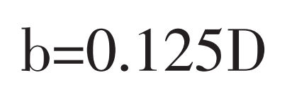
Where B is the tooth width (mm); D is the outer diameter of the end face spiral gear (mm).
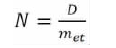
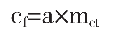
Where n is the number of teeth; D is the outer diameter of end face spiral gear (mm); Met is the modulus of end face (mm).
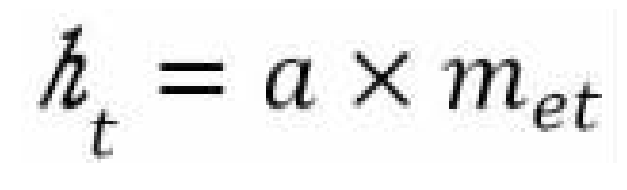
Where HT is the full tooth height (mm); Met is the modulus of end face (mm); A is the coefficient, which is taken as 0.88 when transferring heavy load and 0.616 when transferring light load.
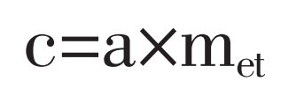
Where C is the clearance between tooth tips (mm); Met is the modulus of end face (mm); A is the coefficient, which is taken as 0.10 when transferring heavy load and 0.07 when transferring light load.
Where CF is the chamfer height of tooth top (mm); Met is the modulus of end face (mm); A is the coefficient, which is taken as 0.09 when transferring heavy load and 0.063 when transferring light load.
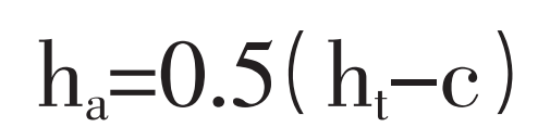
Where HA is the tooth crest height (mm); C is the clearance between tooth tips (mm); HT is the full tooth height (mm).
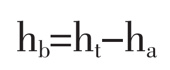
Where Hb is the root height (mm); Ha is the tooth crest height (mm); HT is the full tooth height (mm).
According to the above formula, when transferring light load and heavy load, the full tooth height, tooth top clearance and tooth top chamfer of end face spiral gear are different. At this time, we can measure the full tooth height of the gear according to the generated model and deduce the other parameters.
In addition, the pressure angle of end face spiral gear α 0. According to relevant design data, 30 ° is generally selected, with few special cases. Therefore, it is calculated as 30 °.
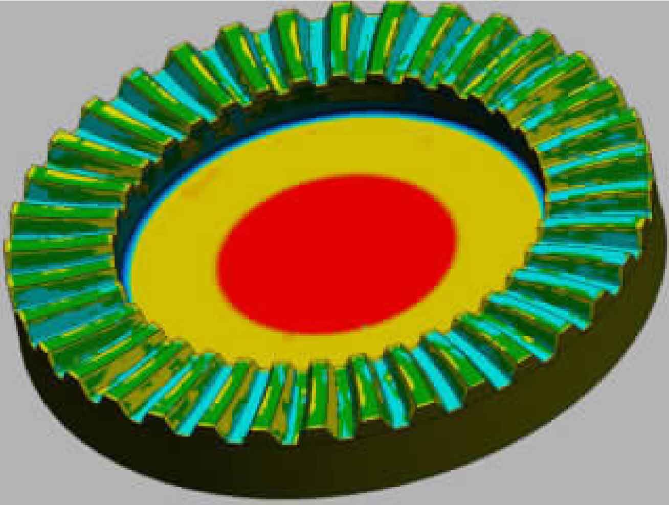
After calculating the gear parameters, we can modify the tooth model of reverse engineering end face spiral gear according to the theoretical parameters. The six surfaces of the existing reverse engineering end face spiral gear tooth model are obtained by dividing the field first and then fitting the surface. The accuracy of patch fitting model will be affected by the different precision of domain division and the actual machining error of parts. At this time, we can make accurate dimensional constraints on some surfaces of the model according to the known parameters and modify the tooth model of end face spiral gear in reverse engineering. The modified tooth model of end face spiral gear in reverse engineering may deviate from the three-dimensional scanning entity, but it is basically within a reasonable range. At this time, the reverse engineering end face spiral tooth gear tooth model is carried out with the reference shaft array, and then the reverse engineering end arc tooth gear is replaced by the other features. The three end model of the whole end face arc gear is basically built. We can use the volume deviation function of Geomagic designx to compare it with the 3D scanning results. The modeling effect is shown in the figure.
Finally, according to the established model, we can select appropriate processing equipment to process the finished product of end face spiral gear. Apply red lead clamping oil on the tooth surface of the finished reverse engineering end face spiral gear and fit it with the matched gear to verify the actual contact. Generally, the contact rate of tooth contact surface is required to be about 70%. If the contact is not good, it is recommended to adjust the tooth model of end face spiral gear in reverse engineering and compare again.
In the process of reverse modeling through Geomagic designx, the difficulties mainly lie in the establishment of coordinate system and the correction of gear tooth model. Many people often insist on completely restoring the physical size of the measured object in reverse modeling, but the greatest significance of reverse engineering is to restore the design idea of a product through the modeling of a product, which most reflects the original design intention of the designer in the model. The research method adopted in this paper has great practical value for the repair and finished product inspection of end face spiral tooth parts without original design drawings.