
The machining process of spiral bevel gear is to first establish the theoretical mathematical model, then convert the mathematical model into an adjustment card, input the gear grinding machine for trial machining, mesh the mark, adjust the machine tool parameters until the mark is qualified, assemble and test the dynamic mark development test, and finally solidify the electronic standard gear.
If there are actual gears, i.e. spiral bevel gears that meet the dynamic requirements after test run, the three-dimensional model of the actual gear can also be obtained through the reverse modeling process. The specific steps are as follows:
Import the actual coordinate points into kimos software as the template gear, open the menu “tooth surface comparison”, compare the template gear with the theoretical tooth surface, and adjust the error between the theoretical data and the template gear until the error value is within 0.003mm.
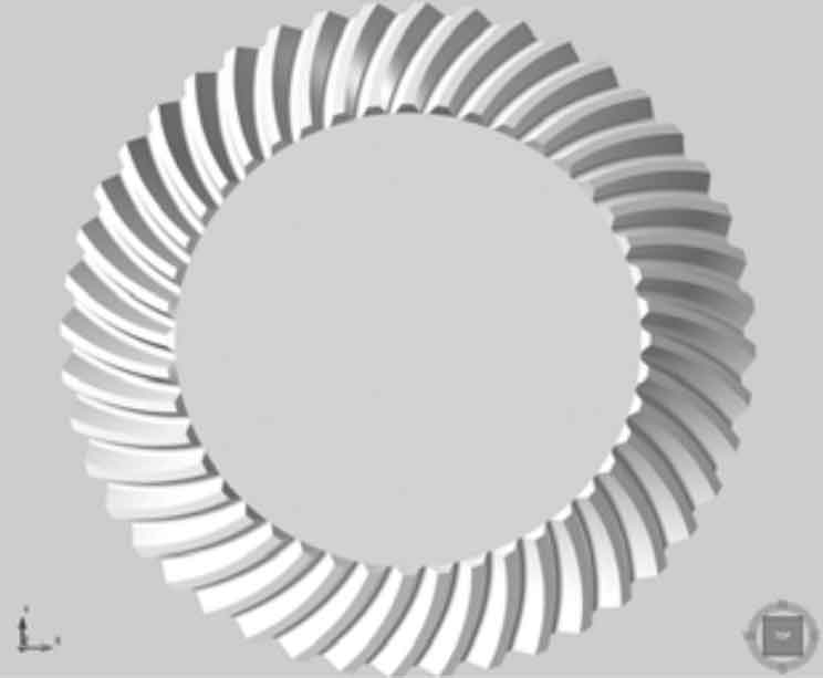
Realize the correction of the theoretical model through the actual gear, and select and modify the parameters of the tool and machine tool to make the theoretical tooth surface consistent with the template gear. The kimos actual model program is obtained by reverse, and the simulation calculation is carried out to generate the three-dimensional solid model of the tooth part of the spiral bevel gear, as shown in the figure.