
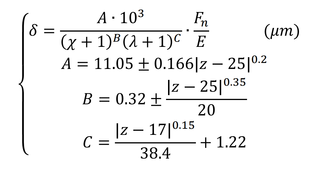
Since the early 1970s, people have begun to use the finite element method to calculate the elastic deformation and tooth root stress of spur gear teeth. At first, it is mainly to calculate the deformation value of single tooth under load. Later, after a large number of finite element calculations of spur gear teeth with various parameters, Wei Renzhi and others obtained the approximate formula of single tooth elastic deformation through regression fitting of the calculation results.
Where: Χ Is the displacement coefficient; Z is the number of spur gear teeth; λ Is the loading position coefficient; FN is the normal load per unit tooth width of spur gear. In the formula, the positive sign is taken when Z < 25, and the negative sign is taken on the contrary. When z > 135, make z = 135.
In the calculation and analysis of the elastic deformation of spur gears, people are mainly concerned about the deformation at the meshing point. In the initial analysis by finite element method, the meshing force of spur gear is generally treated as the concentrated force (meshing force) acting on the meshing point. The deformation of spur gear calculated by this method is actually the deformation of the meshing point of spur gear under the action of concentrated force. In fact, due to the elastic deformation of spur gear teeth, the meshing point actually expands into the contact area, and the contact force is a distributed force, not a concentrated force. Therefore, the finite element method simplifies the distributed force into a concentrated force and the contact area into a contact point, which will produce large errors.
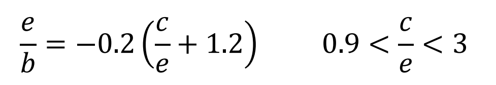
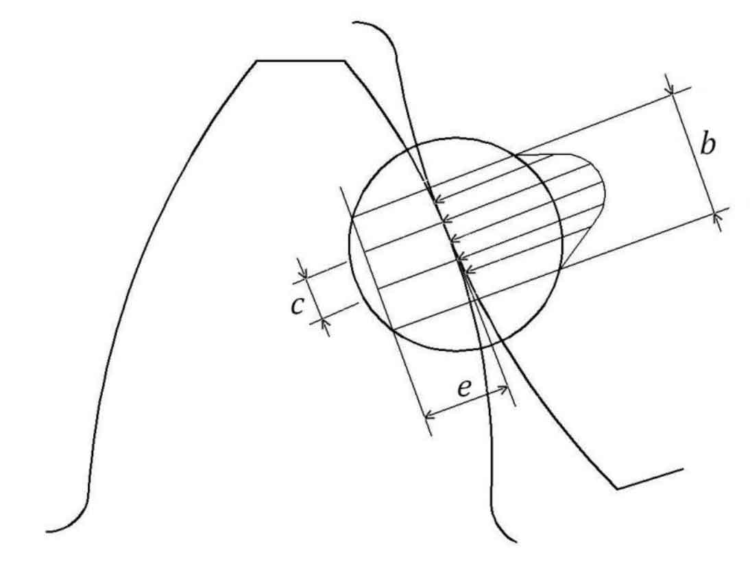
In order to study the above error, J.J. coy et al. Proposed a method to compensate the error by selecting the size of the finite element element in the contact area. They carried out finite element analysis on the cylinder with the same curvature, so as to determine the finite element size to be selected when treating the meshing force of spur gear teeth as concentrated force. Finally, they obtained the following relationship:
Where, B is the width of the contact area, and E and C are the dimensions of the unit in two directions, as shown in the figure.
In the finite element analysis discussed above, single tooth is taken as the analysis object, so the influence of multiple pairs of spur gear teeth meshing at the same time on adjacent spur gears can not be considered in this analysis model. The finite element method of contact problem is a very effective numerical calculation method for calculating non hertzain type contact problem. It is especially suitable for solving the deformation and stress state of multiple pairs of spur gear teeth participating in meshing at the same time. Li Runfang [2] first used this method to analyze the problem of multi tooth meshing. Because of the elastic contact problem, the finite element single method is based on the elastic deformation theory. Therefore, the deformation results calculated by this method actually include the bending deformation, shear deformation, contact compression deformation and other deformation of spur gear teeth. More importantly, because this method can easily embed the spur gear error, when using this analysis model to analyze the meshing contact of spur gear teeth, the static transmission error of spur gear meshing can be easily obtained.