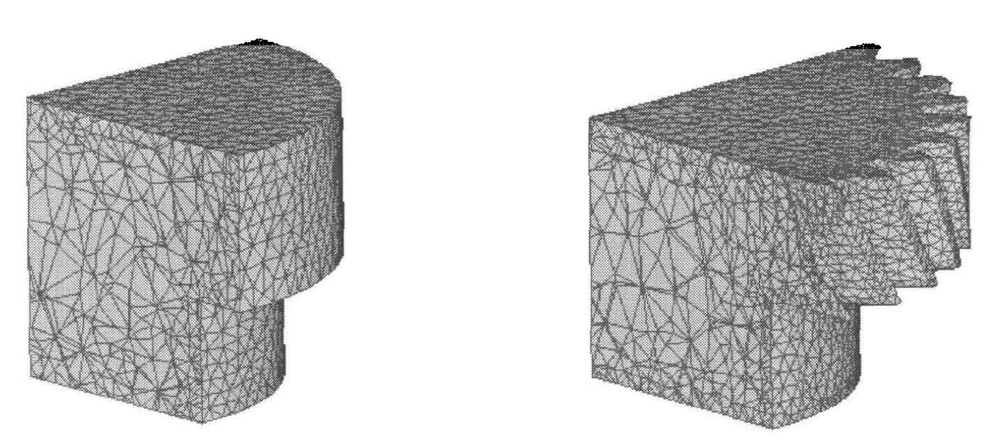
The blank material is DEFORM-3D material library AISI-4120, the temperature is 850 ℃, the temperature effect in heat conduction and deformation between blank and die is ignored, and the upper die speed is 5mm / s. In order to ensure good forming and reduce the time of the initial free pier rough stage of forming, the outer diameter of the blank should be close to the tooth root circle, so the blank diameter is 73.74mm and the lower boss diameter of the blank is 60mm, which is consistent with the boss diameter of helical cylindrical gear. The total height of the blank is 34.4mm of the height of the lower boss. Figure 1 shows the blank shape, and figure 1 shows the forging shape simulated by the closed die forging process.
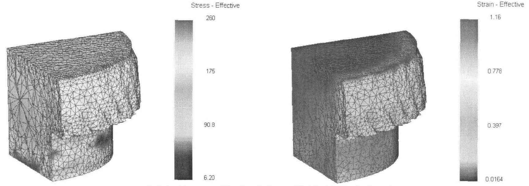
Fig. 2 (a) shows the distribution diagram of equivalent stress and equivalent strain of forging during reduction. At this time, the blank is just filled into the tooth cavity. The stress on the lower boss is small, and the stress on helical cylindrical gear part is large. Due to the restriction of the sleeve, the metal flow at the upper tooth of helical cylindrical gear is slow, and this part of the metal is filled with the die relative to the lower tooth. When metal fills the tooth cavity, the metal flows not only in radial direction, but also in tangential direction. Due to the existence of friction between the surface of die and blank, the stress at the root circle is large, about 200MPa. The blank at the transition arc from involute tooth profile to tooth root circle has large deformation, so the equivalent stress here is large, about 230MPa. At the same time, because the size of the lower boss of the blank is consistent with that of the die, the lower boss of the blank is not deformed. It can be seen from the figure that its equivalent effect variable value is close to 0. Due to the restriction of the sleeve on the metal at the upper end of the blank, the flow of the metal is hindered, and its equal effect variation is small. The metal at the lower end of the blank is first filled with the metal at the upper end to the tooth cavity, where the equal effect variation is large.
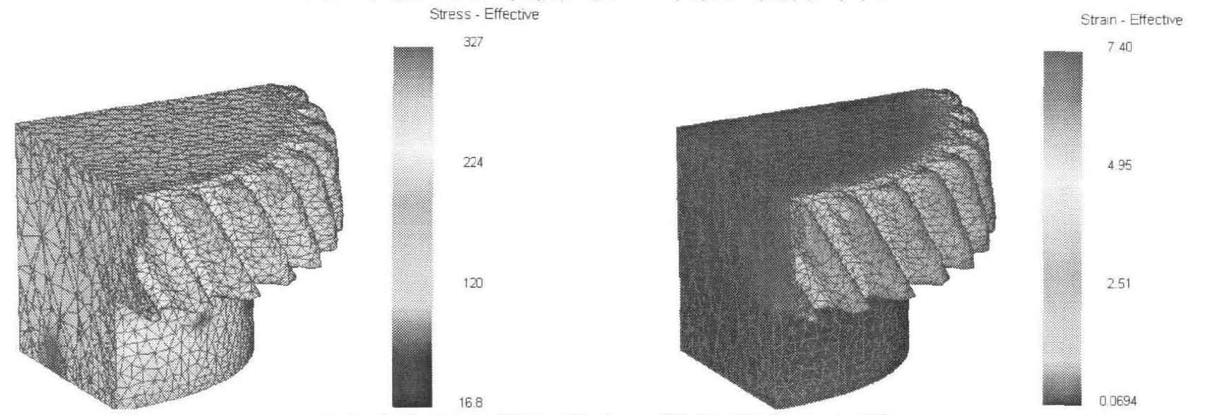
Fig. 2 (b) shows the distribution diagram of equivalent stress and equivalent strain of forgings when the reduction is 80%. At this time, most of the tooth profile is filled, and the tooth cavity at the upper end of the blank is also filled. At this time, the blank is filled to the tooth cavity, there is a large friction between the tooth root and the blank surface, and the equivalent stress at the tooth root is the largest, about 220MPa. Due to the constraint of the sleeve, the filling of the upper end of helical cylindrical gear is slower than that of the lower end. There is only a small amount of metal filling at helical cylindrical gear teeth at the upper end of the gear, and the equivalent stress value here is small, about 130Mpa. The metal at the tooth top has not been filled, and its equivalent force is relatively small. At this time, the metal fills the tooth cavity from the tooth root, which is mainly radial strain. At the same time, due to the existence of helical angle of helical cylindrical gear, there is also tangential strain.
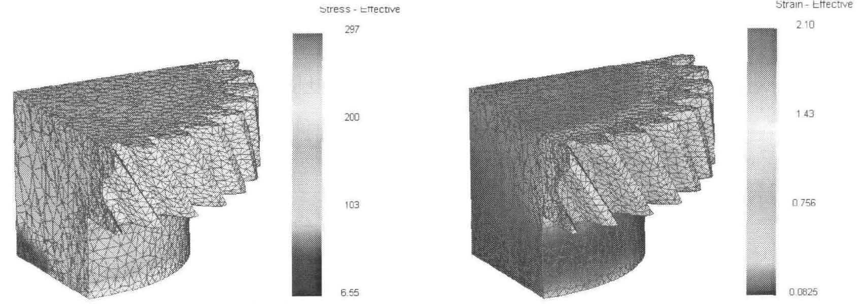
Fig. 2 (c) shows the equivalent stress and strain distribution diagram of the forging when the reduction is 100%. This is the final forming stage of the helical cylindrical gear, and the tooth shape is completely filled. The tooth top and the corner of the upper and lower teeth are filled, where the stress value is the largest, about 270MPa, and the equivalent effect variation at the tooth top is also large.
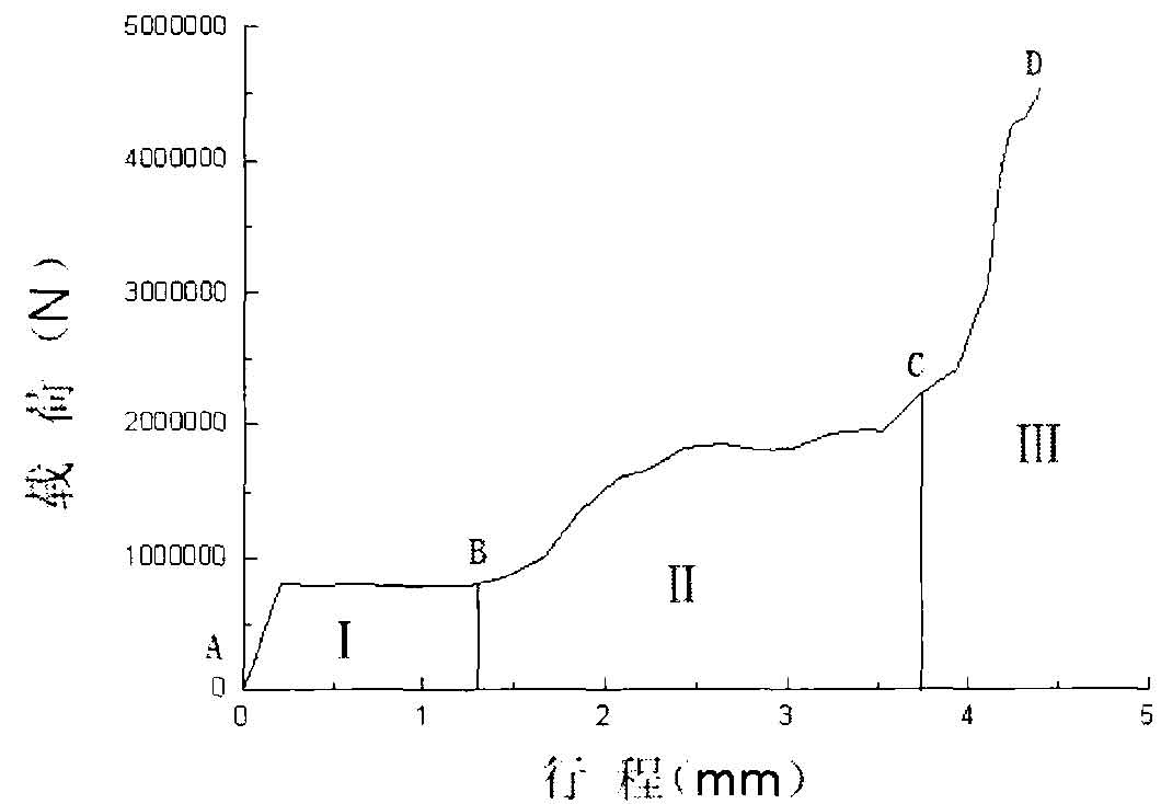
The load stroke curve in the forming process is shown in Figure 3. Through the analysis of load stroke curve, the forming process of helical cylindrical gear is divided into three stages: stage I (AB), which is the initial stage of deformation. This stage is at the beginning of deformation, with short duration and minimum forming force. The deformation of metal is equivalent to the coarse deformation of pier. Stage II (BC) is the dental cavity filling stage. The blank begins to fill into the tooth cavity. With the increase of the filling degree of the blank to the tooth cavity, the deformation resistance and friction resistance increase. On the load stroke curve, the load increases with the increase of the upper die stroke. Stage III (CD) is the final filling stage. The metal has basically filled the tooth cavity, and the blank flow is difficult. To overcome the hydrostatic pressure generated by most of the filled metal in a static state, the working load increases sharply. At this time, the load value reaches the maximum, about 4500kN.

