According to the tool installation pose coordinate system, the spatial hobbing motion coordinate system of tool and cylindrical gear is established (as shown in the figure).
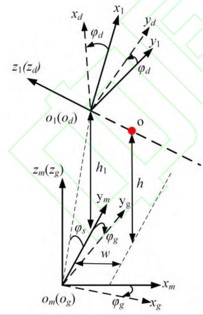
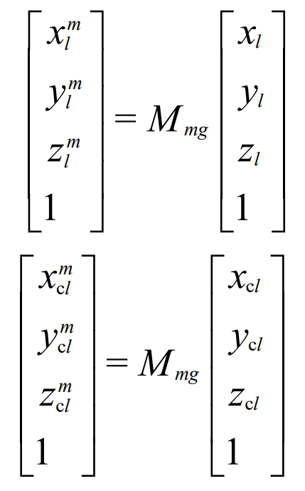
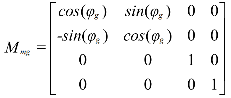
The cylindrical gear dynamic coordinate system og-xgygzg is fixedly connected with the cylindrical gear, and coincides with the cylindrical gear static coordinate system at the initial position; The tool dynamic coordinate system od-xdydzd is reconstituted with the tool static coordinate system at the initial position and is fixedly connected with the tool. In the process of continuous rolling chamfering, the cylindrical gear rotates clockwise around the ZM axis φ g. Clockwise rotation angle of tool around Z1 axis φ d。 According to the spatial motion coordinate system of tool and cylindrical gear shown in the figure, the transformation relationship between each coordinate system is deduced. The coordinate transformation matrix from the cylindrical gear dynamic coordinate system to the cylindrical gear static coordinate system is MMG:
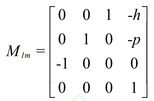
The coordinate transformation matrix from cylindrical gear static coordinate system to tool static coordinate system is m1m:
The coordinate transformation matrix from tool static coordinate system to tool dynamic coordinate system is MD1:
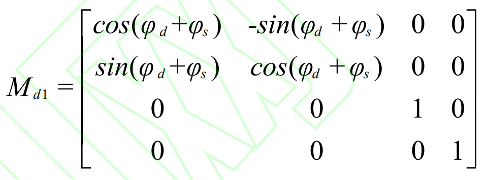
Among them φ S is the included angle between the front edge of the tool and the static coordinate system xmomym surface of the cylindrical gear.
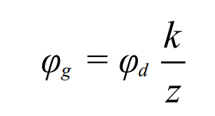
Where k is the number of cutter teeth and Z is the number of cylindrical gear teeth.
The left cylindrical profile and zymm cylindrical profile can be represented in the left cylindrical profile coordinate system.