
When calculating the geometric parameters of hypoid gear, Gleason company specifies detailed steps, and each step has a fixed formula. Gleason algorithm first gives the following initial conditions:
(1) Gear pair transmission ratio or number of large and small gear teeth Z2, Z1;
(2) Axial intersection angle Σ;
(3) Gear pair offset e
(4) Width of large gear tooth surface B;
(5) Large end pitch circle diameter D2 of large gear
(6) Pinion helix angle β ten
(7) Cutter head radius r0 for manufacturing gear machine tool;
In the above conditions, the transmission ratio of gear pair and the shaft intersection angle formed by the axis of large and small gears in space can be determined by the design requirements. For the determination of the number of teeth of large and small gears and the offset distance of gear pair, refer to the design method of quasi double curved surface gear blank, which specifies the determination method of various parameters in detail, such as the sum of the number of teeth of gear pair shall be greater than 40, and the number of teeth of pinion shall not be less than 6. The tooth width of the large gear can be determined by the load and transmitted torque of the gear pair determined by the design requirements and the working environment. The determination method of the large end pitch diameter of the large gear will be introduced in detail. Since the nominal radius of the gear pair is similar to that of the gear pair manufactured by the machine tool, it can be calculated according to the nominal radius of the large pitch gear pair, which is usually matched with that of the small pitch gear pair manufactured by the machine tool. When judging whether the spiral direction is left-hand or right-hand, it should be seen from the top of the bevel gear to the tooth surface. If the tooth line tilts left from the small end to the large end, it is called left-hand rotation, and if it tilts right, it is called right-hand rotation. The rotation direction of the driving and driven bevel gears is opposite.
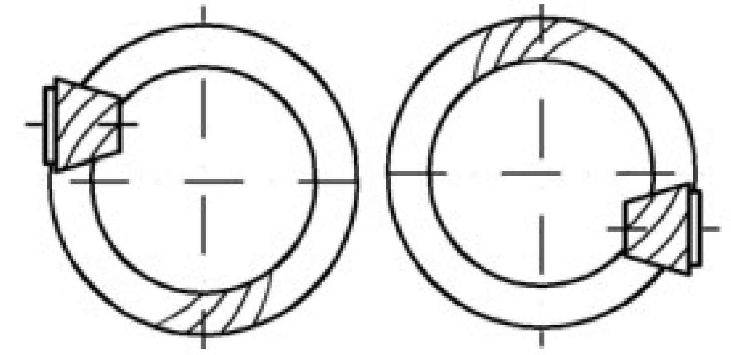
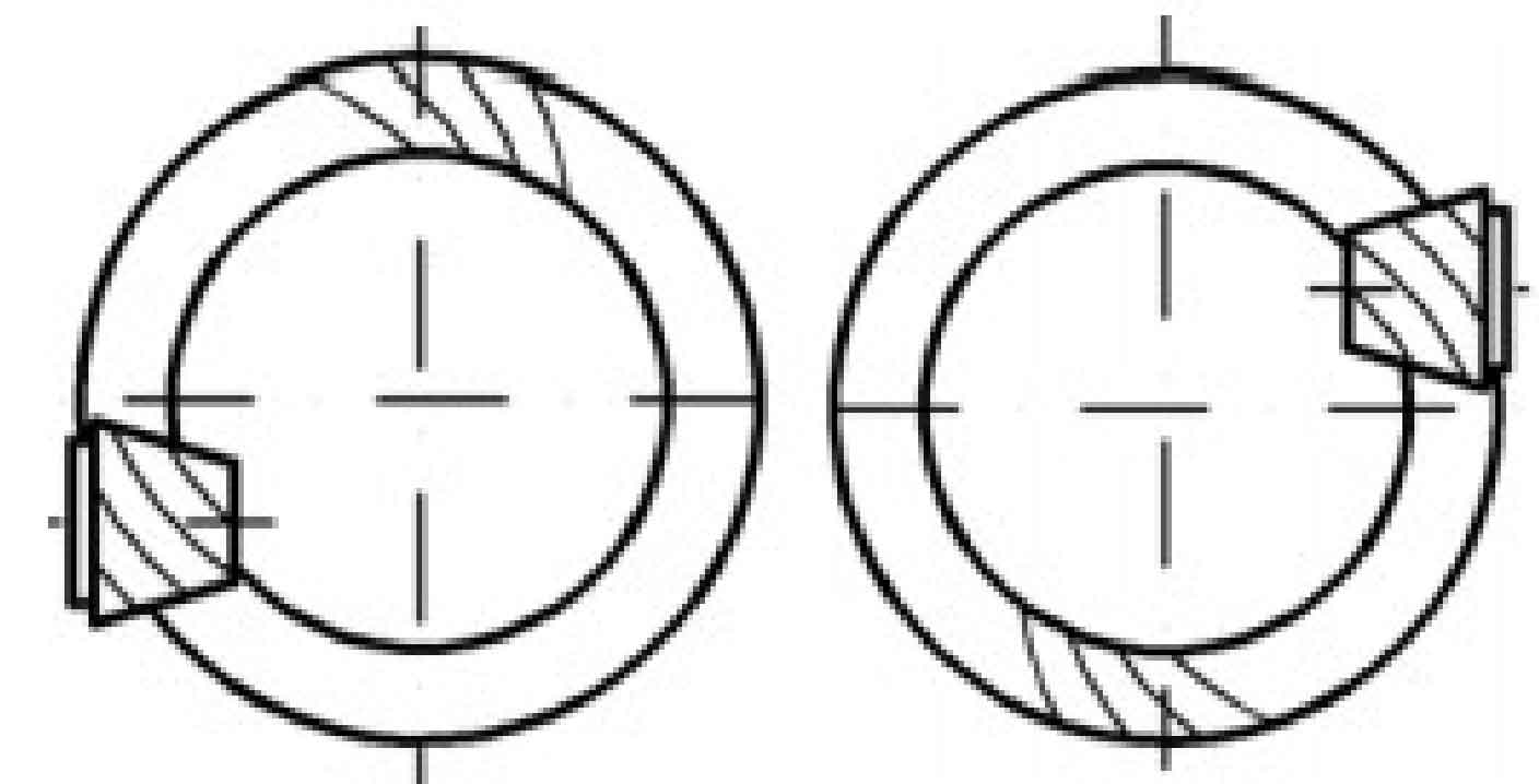
The offset direction of hypoid gear can be divided into up offset and down offset, and the offset direction is determined as follows: look from the conical top of the driven gear to the conical surface, and make the driving gear on the right. If the driving gear axis is above the centerline of the driven gear, it is up offset, and below the centerline of the driven gear, it is down offset. As shown in Figure 1, when the upper offset, the spiral direction of the driving gear is always right-handed, and the driven bevel gear, that is, the big gear, is left-handed; As shown in Figure 2, when downward offset, the pinion always rotates to the left and the big gear rotates to the right. In this way, it can ensure that the large and small wheels have the axial force to push away from each other on the working surface, so that the meshing clearance of the hypoid gear tends to increase, so as to push the active and driven wheels away from each other, so as to avoid the bite caused by overheating of the hypoid gear.