
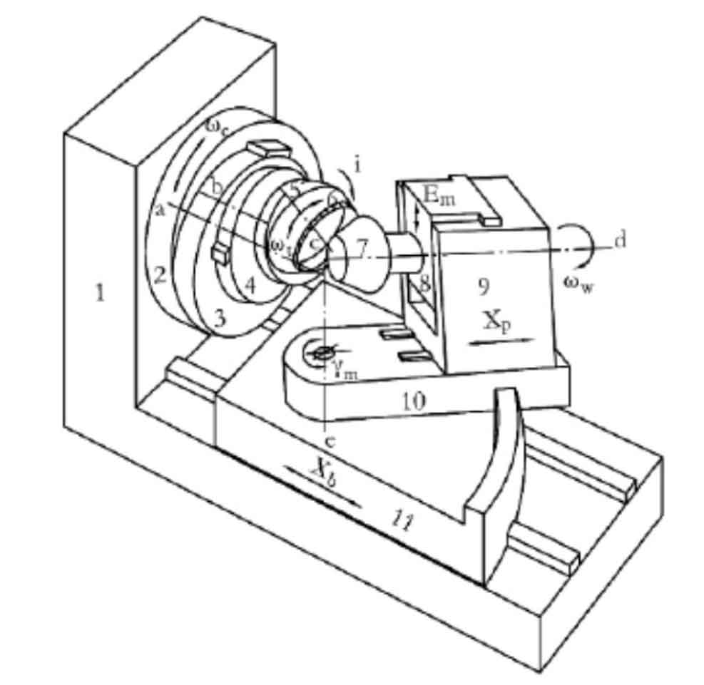
In the spiral bevel gear milling machine with traditional mechanical structure, the rotating shaft of the cutter head is installed on the shaking table, and it rotates itself while swinging with the shaking table in the process of machining the gear tooth surface. At this time, the spatial motion path of the cutting edge of the cutter teeth installed on the cutter head is the tooth surface of the forming gear teeth. The gear blank is installed on the rotary shaft of the offset support plate and rotates around its axis in the processing process. The relative motion between the tooth surface of the generating gear and the gear blank forms the hobbing and gear cutting motion. The offset bracket drives the gear blank to move up and down along the guide rail of the machine tool, so as to adjust the vertical gear position of the tooth surface processing. The tooth surfaces of gears processed by different vertical gear positions are different. When it is zero, the rotation axis of the gear blank and the rotation axis of the production wheel intersect at a point in space. At this time, the tooth surface formed on the gear blank is the tooth surface of the spiral bevel gear; When it is not zero, the rotation axis of the gear blank and the rotation axis of the production wheel intersect in space and form an axial offset. At this time, the tooth surface formed by machining on the gear blank is a hypoid gear tooth surface. The basic structure of traditional mechanical gear milling machine is shown in the figure.
On the traditional gear processing machine tool, the rotary base is equipped with a horizontally moving guide rail, and the workpiece support can drive the gear blank to move back and forth along the guide rail, so as to realize the adjustment of axial gear position in spiral bevel gear processing. The rotary base can drive the workpiece support to rotate along the arc-shaped track on the bed saddle, so as to adjust the installation angle of the gear blank. The depth of gear tooth processing is adjusted by the movement of the rotary base, workpiece support and gear blank on the saddle driven by the bed guide relative to the center of the machine tool.
After the tooth surface processing starts, the feed drum drives the bed saddle and its auxiliary parts as well as the gear blank to move to the correct position of meshing with the hypothetical tooth surface. At the same time, the shaking table drives the cutter head and the gear blank to rotate around their respective axes with a certain roll ratio under the action of generating the transmission chain, and the cutting edge on the cutter head gradually processes a tooth groove on the gear blank. After machining a tooth groove, the bed saddle drives the gear blank to retreat. After the gear blank rotates a certain angle around its axis, the shaking table drives the cutter head to rotate to the position of the initial cutting, ready to process the next tooth. Carry out the cycle of the above processing process for many times. After cutting all tooth surfaces, the gear milling machine will stop processing.