The cylindrical gear of reducer bears the random load of road surface and the load of driving motor at the input end transmitted by the wheel and half shaft. The remarkable characteristic of these loads is that they are highly random and unpredictable with changes, and their characteristics can only be described and analyzed by statistical methods. Counting method is the main method for random load data processing. Its essence is to calculate and accumulate the occurrence times of different amplitudes in random load by combining miner’s law of fatigue damage theory.
At present, there are many methods for cycle counting. For the automotive industry, the rain flow counting method is mainly used. Scholars have described in a large amount of space that the rain flow counting method is not suitable for cylindrical gears, because the object of rain flow counting needs a continuous load history. For a pair of meshing cylindrical gears, the load is continuous, but for a single tooth, the load is discontinuous, the tooth load is a pulsating cyclic load, and the stress is a process from 0 to the maximum and then to 0, so the tooth load cannot be counted by the traditional rain flow counting method, It is described in detail.
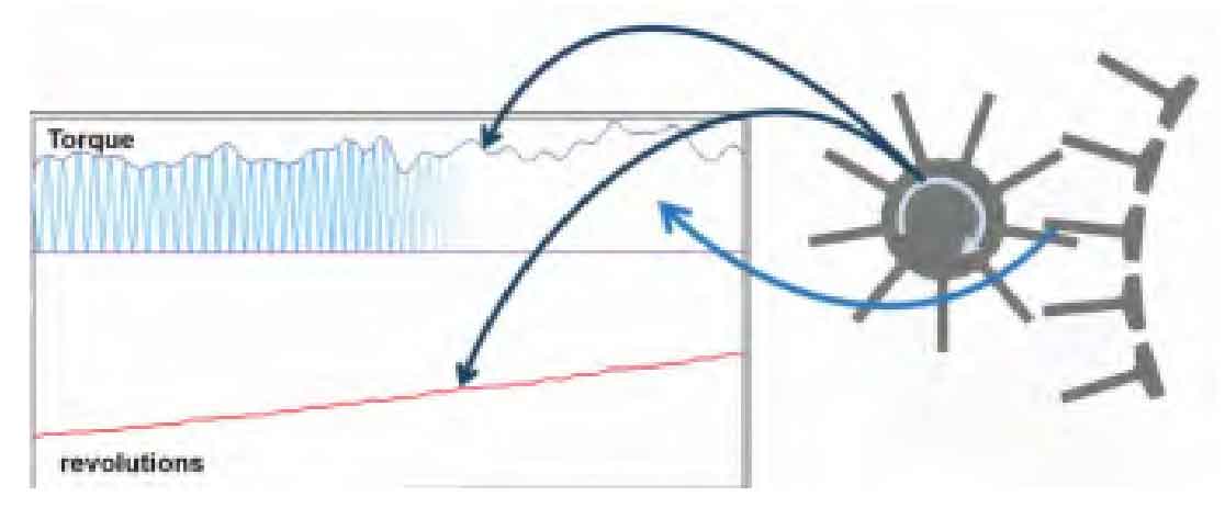
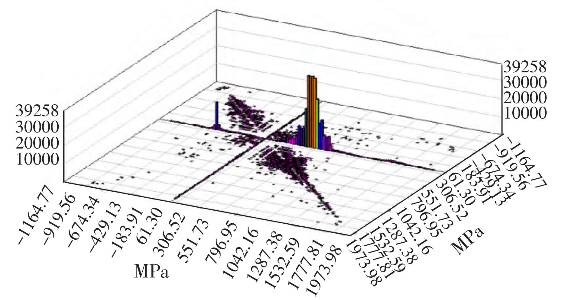
In view of the above analysis, the rotating rain flow counting method is used for cycle counting. The schematic diagram of rotating rain flow counting is shown in Figure 1. In the figure, torque is the torque transmitted by the cylindrical gear pair, and revolutions is the speed of the cylindrical gear pair. The load spectrum of a single tooth can be outlined on the load spectrum of the cylindrical gear pair according to the real-time speed. Each segment of the cylindrical gear load spectrum outlined by this method is similar to a triangle, and its value conforms to the process from 0 to peak and then to 0. Where: stress ratio r = 0, amplitude and mean value are( σ a+ σ m) / 2, if the differential method is used in an infinitesimal time, a more accurate cylindrical gear load spectrum can be obtained, which lays a foundation for the subsequent schematic diagram of rotating rain flow counting in Figure 1 to a more practical cylindrical gear life. Using tecware to count the rotating rain flow, the results are shown in Figure 2.