
Due to the inevitable machining error and heat treatment deformation, the actually processed gear tooth surface often deviates from the theoretical design tooth surface or the standard gear tooth surface, and due to the general backwardness of domestic heat treatment technology, this deviation will be larger, sometimes up to hundreds of microns, which leads to the obvious deviation of the contact area position and contact trace of the paired gear pair from the pre-designed position, the increase of transmission error and the unstable meshing, Produce vibration and noise, and even cause edge contact and stress concentration, resulting in premature failure of the gear pair. Therefore, the gear tooth surface error must be corrected, and the correction of the gear tooth surface error is based on the accurate measurement of the actual tooth surface and the theoretical design tooth surface error.
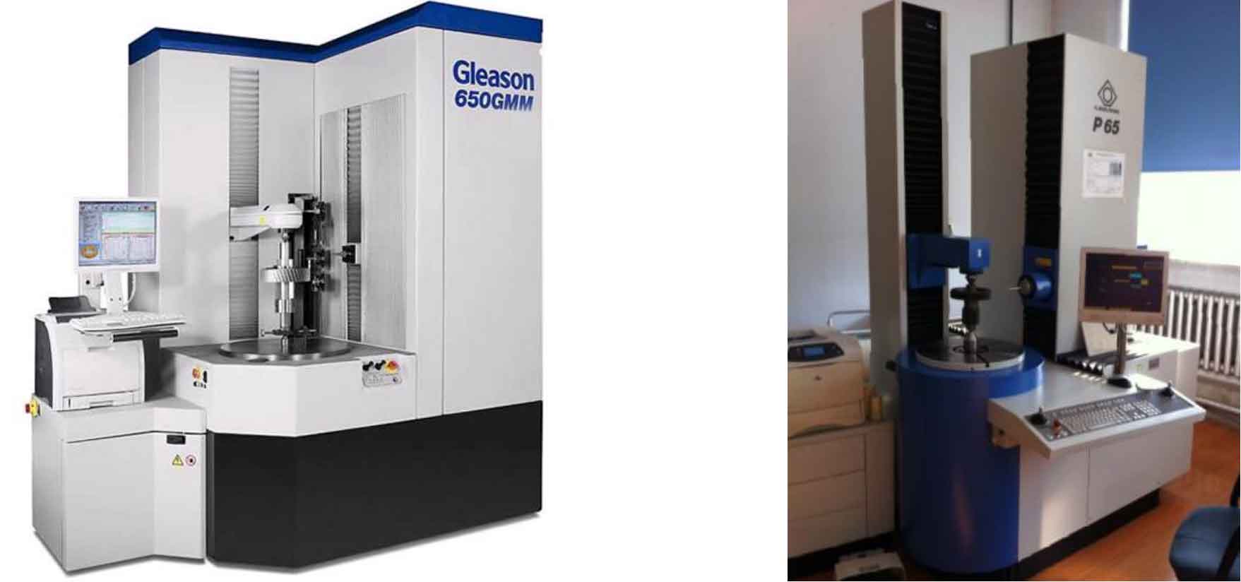
In recent years, the emergence of high-precision CNC gear measurement center based on coordinate measurement principle makes the accurate detection of tooth surface error possible. For example, m&m gear measurement center of Gleason company (Figure 1), P-Series gear measurement center of klingelberg company (Figure 2) and 3903 gear measurement center of China’s Harbin quantum group (Figure 3), etc. For gears, coordinate measurement is to take the measured gear as a pure geometry, obtain the tooth surface coordinate data of the actual gear through measurement, and compare it with the theoretical tooth surface, so as to obtain the gear tooth surface error. Compared with mechanical generative measuring instruments, the biggest advantage of CNC gear measuring center is that it provides the possibility to measure the tooth surface of gears with complex shapes, such as the small tooth surface of hypoid gear pair with great deflection.
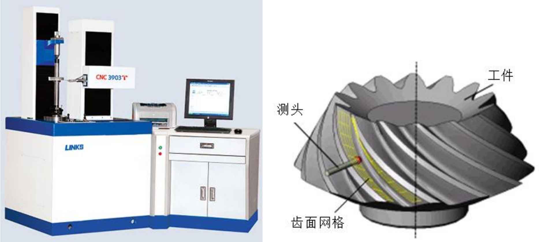
In order to control the geometric accuracy of the machined gear tooth surface, the tooth surface accuracy control technology based on the actual tooth surface measurement has appeared since the 1980s. This technology refers to the measurement of the tooth surface coordinates at the mesh nodes of the actual tooth surface before and after heat treatment on the CNC gear measurement center or coordinate measuring machine (CMM) according to the predetermined grid covering the whole tooth surface (Fig. 4). According to the measurement results, Identify the source of gear tooth surface error and calculate the tooth cutting correction, and adjust the processing parameters according to the calculation results, so as to minimize the error between the actual gear tooth surface processed after the processing parameters are adjusted and the theoretical design tooth surface, standard gear tooth surface or optimal tooth surface. This is an active gear tooth surface pre correction technology, that is, in the trial production stage, through the analysis of the measurement results of the actual gear tooth surface, and with the help of the sensitivity coefficient matrix, The corresponding adjustment amount of machining parameters is obtained by solving, and then the adjusted machining parameters are used for gear cutting to pre compensate the machining error and the gear tooth surface error caused by heat treatment deformation.
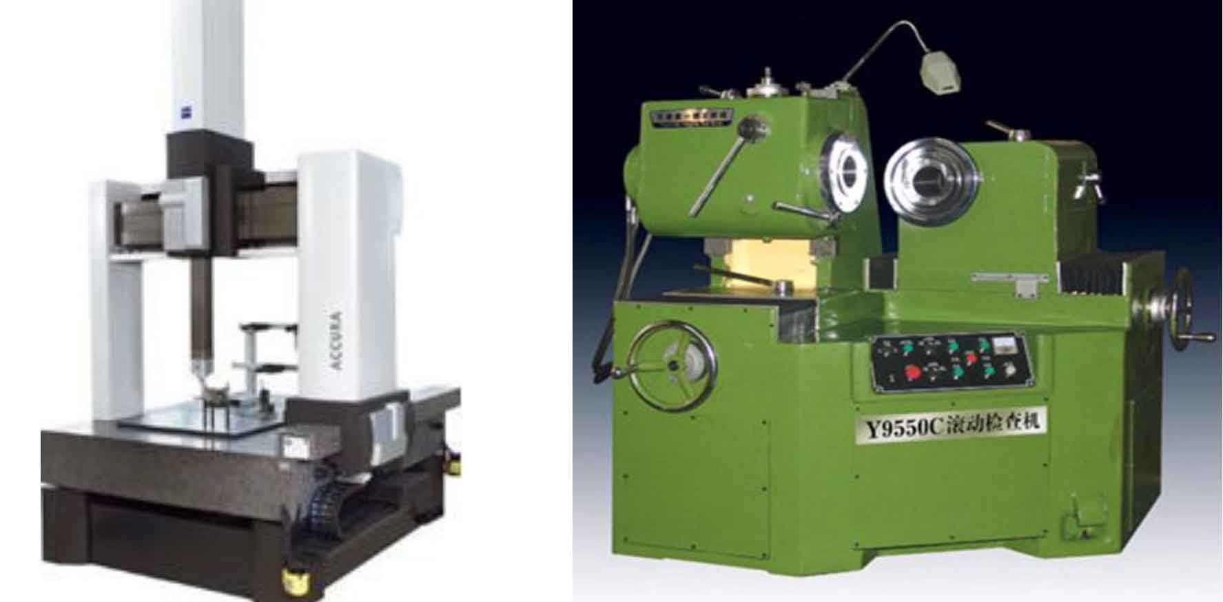
In 1987, Gleason developed the first gear machining accuracy control system based on real tooth surface CMM, which uses Zeiss CMM (Fig. 5) as the measuring equipment. In the same year, caterpillar developed a special gear measurement design and corresponding software, but the specific control methods were not disclosed. In the 1990s, Gleason company developed the tooth surface error correction technology based on tooth surface coordinate measurement. This method uses the tooth surface coordinate measurement, and uses the tooth surface error correction technology to reduce the error of each step of the tooth surface to the minimum value. The evaluation of the tooth surface error of the gear is completed by using the root mean square of the error. Using Gleason cagetm4win software module to calculate the tooth surface modification of the gear, the adjustment parameters of the machine tool can be obtained automatically, Only one or two trial cuts are needed to complete the correction of the contact area, replacing the complex process of adjustment and calculation by the traditional rolling inspection machine (Fig. 6), but as one of Gleason’s core technologies, this technology is not publicly available.
In 1991, Litvin proposed a function method for gear tooth surface error compensation, which is essentially different from Gleason’s reverse modification method in principle. This method regards the point vector on the gear tooth surface as a function of the machine tool’s adjustment parameters, and the error is considered to be the projection of the differential increment of the point position vector in the normal vector direction of the point, because it is approximately equal to the distance between the theoretical tooth surface and the real tooth surface along the normal vector direction of the point, Therefore, the coordinate measurement value of each point on the gear tooth surface can be directly used to describe the error of this point. The error source and compensation calculation are based on the differential expression of this vector function, but the number of points measured on the gear tooth surface is generally more than 45 points, which is much larger than the number of machine tool adjustment parameters. Therefore, the gear tooth surface error identification equation group established according to all gear tooth surface measurement points is an overdetermined equation group. At the same time, Due to the coupling effect of machine tool adjustment parameters on the geometric structure of gear tooth surface, the solution of this equation group is difficult and prone to morbidity. Gosselin et al. Analyzed the influence law of a single machine tool adjustment parameter on the tooth profile error, selected some machine tool adjustment parameters as optimization variables, established an error sensitivity matrix based on the unit increment of machine tool adjustment parameters, and obtained the correction of machine tool adjustment parameters by solving the error compensation equation. In view of the shortcomings of Litvin method, Lin proposed a new modified optimization method. This method introduces the actual adjustment range of machine tool adjustment parameters as the constraint condition of the equation group, but it is essentially the same as the method proposed by Litvin. Wang Yanzhong and others have also conducted similar research. Gabiccini, Li Jingcai, etc. improved it by using different equation solving methods. Tang Jinyuan, Cao Kang, etc. studied the influence of machine tool adjustment parameters on the tooth surface error of hypoid gear pinion machined by the denaturing method, obtained the adjustment parameters that have a great influence on the tooth surface error of gear based on the SFT machining method, and proposed the minimum parameter correction method of gear tooth surface error. Wang Zhiyong et al. Established the tooth profile error correction method of spiral bevel gears based on proportional correction parameters. Using the optimization algorithm, the correction times of various proportional correction parameters can be obtained, and then the correction amount of machine tool adjustment parameters can be obtained. Wang Jun and Wang Xiaochun gave the planning method of measuring grid of Gleason spiral bevel gear, and discussed the positioning and measuring method of spiral bevel gear on CMM. According to the measurement results of the actual tooth surface, the deviation between the theoretical tooth surface and the actual tooth surface is described by the difference surface. Using the characteristic parameters of the difference surface, the correction value of the parameters of the gear cutting machine tool can be solved quickly and stably, and the machine tool parameters that need to be corrected are the least. On the basis of universal motion control (UMC) design software, fan proposed using high-order universal motion to correct the high-order error term of the tooth surface of face milling, and studied the law of the change of the gear tooth surface caused by the change of the general motion model coefficient. The general motion correction coefficient can be achieved by the optimization algorithm aiming at the minimum error of the gear tooth surface, On this basis, the high-order error correction technology of FH bevel gear is also studied. Ship puts forward a method of gear tooth surface error correction directly for 6-axis CNC machine tools, which can be completed by high-order control of each moving axis. However, most of them focus on single-sided machining, and there are few reports on the tooth surface error correction of cycloid constant height bevel gears and hypoid gears processed by double-sided machining.
As an advanced gear tooth surface accuracy control method, the current demand for gear tooth surface error pre correction is mainly reflected in the following two aspects:
First, for gears that can be shaped after heat treatment (such as Gleason involute teeth can be ground, and “gram” cycloid teeth can be scraped), because the thickness of the heat treatment layer is thinned and becomes uneven, resulting in the reduction of the contact strength of the gear tooth surface and the deterioration of corrosion resistance, manufacturers are increasingly inclined to minimize or do not remove the heat treatment layer material to retain the thickness of the heat treatment layer;
Second, for gears that cannot be shaped after heat treatment (such as “Austrian” Cycloid Teeth), the process of heat post grinding can only improve the gear tooth surface finish, and the pre correction of gear tooth surface error becomes a good choice.