
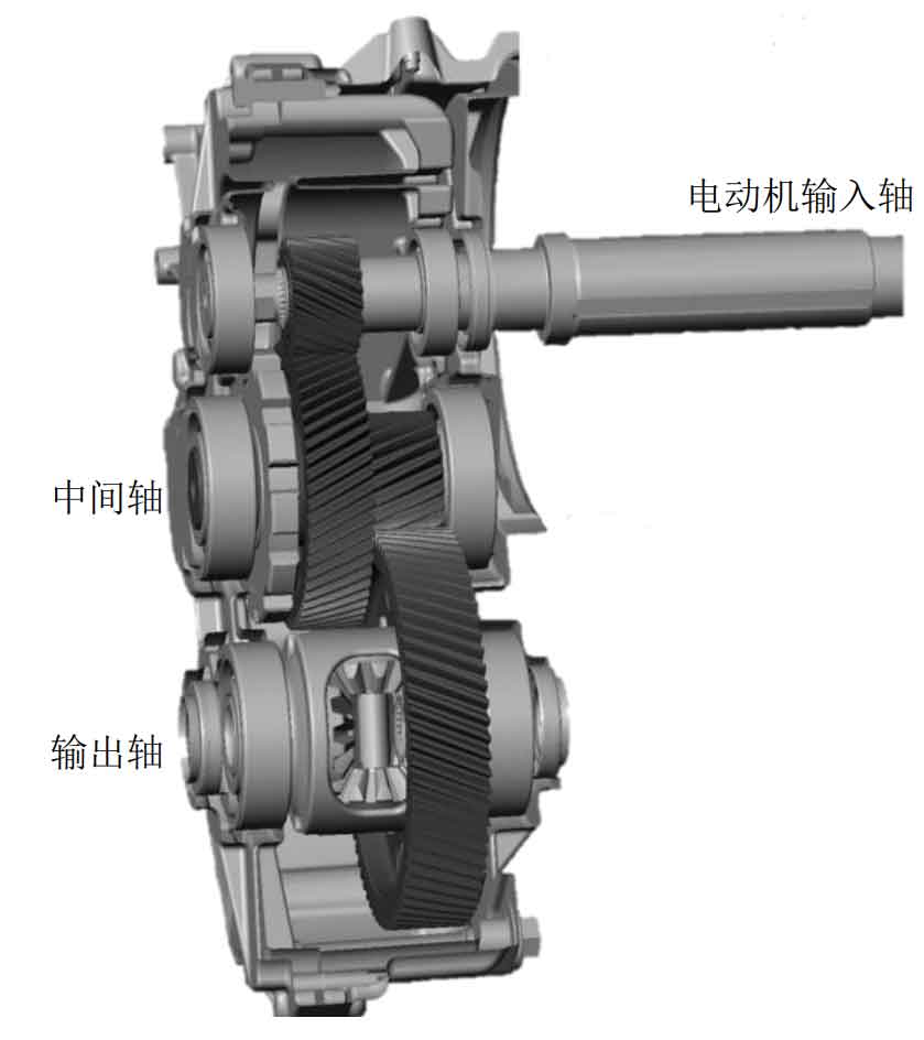
The high-speed helical gear drive of an electric vehicle is taken as the research object, and its structure diagram is shown in Figure 1. The motor directly inputs the power into the reducer, and then transfers it to the vehicle half shaft after two-stage helical gear reduction. In order to study the vibration characteristics of single-stage high-speed helical gear transmission, a 6-DOF bending torsion shaft dynamic model of the reducer input stage tooth pair in the figure is separately established, as shown in Figure 2.
The differential equations of the dynamic model in Figure 2 are listed as follows:
Wherein, m1p and m1g are the two gears
Quality; R1 p and R1g are the base circle radius of the input end teeth to the two gears; Tin is the system torque; T1g is the torque of input gear; Y1p and z1p are the vibration displacement of input stage pinion in y and z directions; Y1g and z1g are the vibration displacement of input stage big gear in y and z directions; θ 1p 、 θ 1g is the torsional displacement of input end teeth to two gears; K1y and k1z are the equivalent support stiffness of input stage pinion in y and z directions; K23y and K23z are the equivalent support stiffness of the intermediate shaft in the y and z directions; C1y and c1z are the equivalent support damping in the y and z directions of the intermediate axis respectively; C23y and c23z are the equivalent support damping in the y and z directions of the intermediate shaft respectively; Fs1 is the meshing impact force of the input end tooth pair.
Based on the force and displacement decomposition, the tangential dynamic meshing force and axial dynamic meshing force of the input end tooth pair are expressed in parameter form as shown in Formula (2):
Wherein, k1 (t) represents the time-varying meshing stiffness of the input end gear pair; β 1 is the helix angle of input end tooth pair; α Is the pressure angle; Cm1 is the meshing damping of the tooth pair at the input end.
The calculation formula of meshing damping is shown in Formula (3):
Where: ζ The damping ratio is 0.1.
In order to eliminate the influence of helical gear rigid body angular displacement on subsequent analysis, relative angular displacement is introduced
q. The angular displacement is converted into linear displacement, and its expression is shown in Formula (4):
Substituting equation (4) into equation (1), the torsional vibration equation can be simplified as:
Where, m1 is the equivalent torsional mass of the input end tooth pair, and its expression is shown in Formula (6):