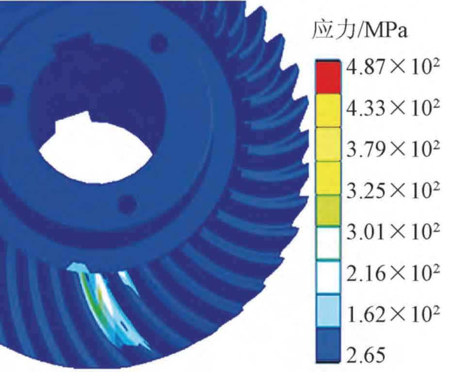
The equivalent stress nephogram and equivalent displacement nephogram of spiral bevel gear under stable working condition are shown in Fig. 1 (a) and Fig. 1 (b) respectively. It can be seen from Figure 1 (a) that the maximum equivalent strain occurs at the contact of the driven gear tooth surface, and its value is 1 396 × 103 m。 Figure 1 (b) is the stress nephogram of two pairs of teeth meshing; It can be seen from the stress nephogram of spiral bevel gear that the stress is mainly concentrated at the contact part and tooth root. The maximum meshing stress at this position occurs at the tooth root where the pinion meshes into the tooth, and the maximum stress value is 311 37MPa, less than the allowable contact fatigue stress of the material.
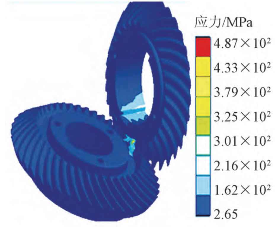
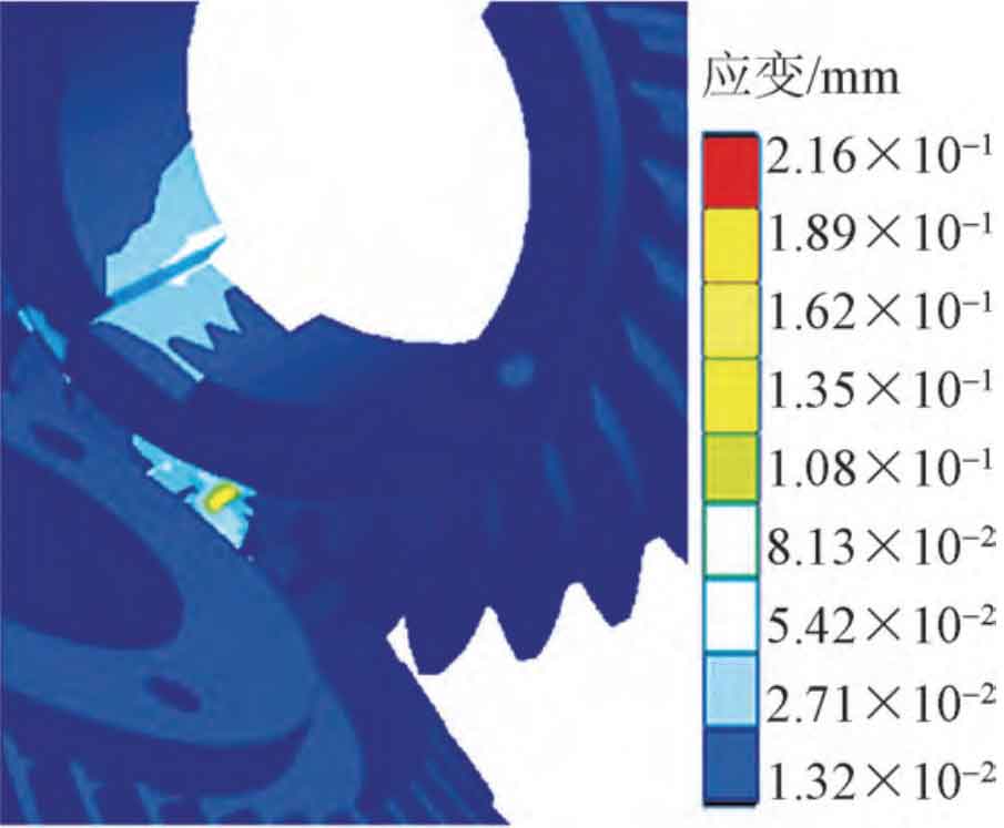
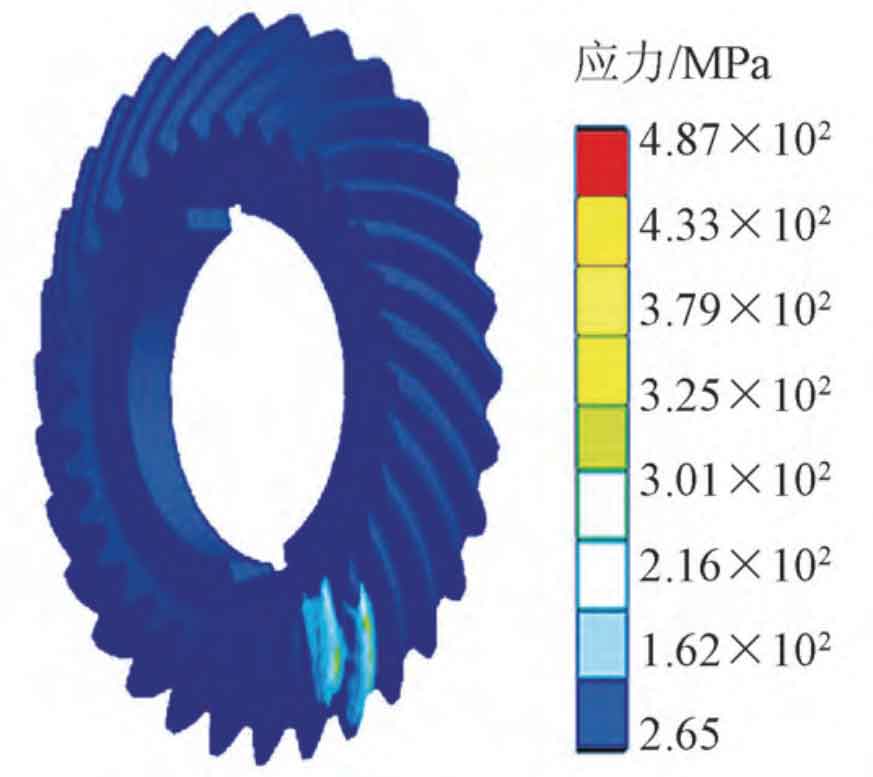
Figure 2 shows the total contact stress nephogram of the large and small gears when considering friction, and the maximum contact stress is 278 208MPa and 311 37 MPa。 By comparing Figure 2 (a) and Figure 2 (b), it can be seen that the stress and strain at the contact position of the spiral bevel gear pair is the largest during operation. The tooth root stress of the spiral bevel gear is consistent with the moving direction of the contact mark. Because the contact stress is much larger than the tooth root stress, the tooth root stress is not obvious.