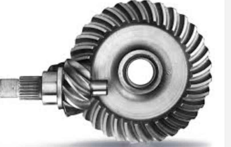
Gear geometry and tooth contact analysis are crucial aspects of designing and analyzing hypoid gear systems. Hypoid gears are a type of gear system used to transmit power between non-intersecting, non-parallel shafts. They are commonly found in automotive differentials, power tools, and heavy machinery.

To understand gear geometry and tooth contact analysis in hypoid gear systems, let’s break it down into two parts: gear geometry and tooth contact analysis.
1.Gear Geometry:
Gear geometry involves determining the shape, size, and specifications of the gear teeth. In hypoid gears, the teeth are curved and have a complex geometry due to the non-parallel shafts. The gear geometry parameters include:
- Pitch diameter: The theoretical diameter of the gear at the point where the teeth mesh.
- Gear ratio: The ratio of the number of teeth between the input and output gears.
- Pitch angle: The angle between the gear’s tooth and its axis.
- Helix angle: The angle between the gear’s tooth trace and the gear’s axis.
- Offset: The distance between the gear’s axes of rotation.
- Backlash: The clearance between mating gear teeth.
2.Tooth Contact Analysis:
Tooth contact analysis focuses on evaluating the contact patterns and performance of the gear teeth during operation. The goal is to ensure proper load distribution, minimize stress concentrations, and maximize gear life. In hypoid gear systems, due to the non-parallel shafts and complex tooth profiles, tooth contact analysis becomes more challenging compared to other gear types.Tooth contact analysis involves the following steps:
- Meshing analysis: This determines the location and amount of tooth contact along the gear face width. It ensures that the teeth engage smoothly without interference.
- Load distribution analysis: This evaluates how the load is distributed among the gear teeth to avoid excessive stress on individual teeth. It helps optimize the gear geometry for load sharing and minimizes the risk of tooth breakage or wear.
- Contact pattern analysis: This analyzes the contact patterns between gear teeth to assess the quality of tooth engagement. The goal is to achieve a favorable contact pattern with proper alignment, minimizing edge loading and tooth surface distress.
Gear geometry and tooth contact analysis in hypoid gear systems are crucial for ensuring the efficient and reliable operation of these complex gear systems. Proper design and analysis of gear geometry and tooth contact patterns help optimize performance, minimize wear, and increase gear system lifespan.
