
1 Research background
Helical bevel gear is a key part of mechanical equipment, widely used in helicopters, automobiles and other transmission systems, the quality of helical bevel gears is directly related to the service life of mechanical equipment. The heat treatment and grinding process is an important process step for helical bevel gears, which will affect the helical bevel teeth The surface integrity of the wheel has an impact, such as the presence of residual stress on the tooth surface. In the production process, gear heat treatment and residual stress detection after grinding are more labor-intensive and material-consuming, and the application of finite element simulation analysis methods can greatly shorten the detection cycle and save costs. Therefore, the mathematical analysis model of gear heat treatment and grinding process is established by computer simulation method, which has certain practical application significance.
In terms of numerical simulation of gear heat treatment, Sugianto et al. studied the residual stress and microstructure distribution of gear teeth after carburizing and quenching of SCr420H steel helical gears. Lee Geunan applied numerical simulation methods to study the deformation of gears during carburizing and quenching process. Sun Yonggang et al. through there is The limiting element method studies the effects of temperature, stress, carbon diffusion, etc. on large interiors Effect of heat treatment of ring gear; Du Guojun et al. carried out numerical simulation of the quenching process of 20CrMnTi steel gear, and studied the influence of different permeable layer thicknesses on the residual stress distribution. Zhu Jingchuan et al. applied ABAQUS software to calculate the temperature field and stress field of the bevel gear workpiece. Aiming at the metal grinding problem, Wang Haining et al. established a grinding model of single-particle cubic boron nitride abrasive particles, and applied Deform-3D software to study the influence of grinding parameters on residual stress. Qu Wei used ANSYS software to simulate the residual stress of diamond grinding wheel grinding cemented carbide; Huang Xinchun et al. studied the mechanism of residual stress during the grinding process of superalloy, and discussed the influence of residual stress on fatigue life. Li Wan, et al. According to the forming process of surface gears, a calculation model of force and thermal coupling and residual stress of the tooth surface was established. sheet Yinxia et al. studied the influence of diamond roller dressing parameters on the residual stress of high-strength steel grinding. Wang Chuanyang et al. studied the residual stress influencing parameters of EA4T steel in the grinding process. Based on previous studies, no coupling analysis of heat treatment and grinding processes has been performed. The author applied DEFORM and ABAQUS software to establish a three-dimensional finite element analysis model of the carburizing quenching and grinding process of helical bevel gears, obtained the residual change process and law of helical bevel gears after coupling heat treatment and grinding process, and analyzed the helical bevel teeth with different grinding parameters The influence of wheel residual stress, so as to guide the actual production process to control the stress and deformation of gear processing, improve the performance of helical bevel gear, and extend the service life.
2 Helical bevel gear heat treatment simulation
2.1 Heat treatment process route
The material of the helical bevel gear is 12Cr2Ni4A steel, the chemical composition is seen
Table 1, the mechanical properties are shown in Table 2.The heat treatment process of 12Cr2Ni4A steel helical bevel gear is normalizing, quenching, tempering, carburizing, cryogenic treatment, low temperature tempering, and the process route is shown in Figure 1.
Table 1 Chemical composition of 12Cr2Ni4A steel
| element | Quality score |
| C | 0. 10% ~ 0. 150% |
| Mn | 0. 30% ~ 0. 60% |
| Si | 0. 17% ~ 0. 37% |
| Cr | 1. 25% ~ 1. 75% |
| Ni | 3. 25% ~ 3. 75% |
| P | < 0. 025% |
| S | < 0. 015% |
Table 2 Mechanical properties of 12Cr2Ni4A steel
| 项目 | 数值 |
| 屈服强度/MPa | 1 080 |
| 抗拉强度/MPa | 1 175 |
| 延伸率 | 12% |
| 断面收缩率 | 55% |
| 冲击韧性/( J·cm - 2 ) | 80 |
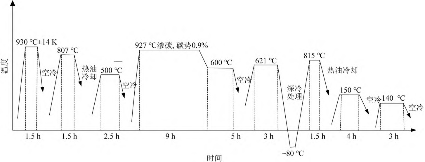
▲Figure 1 Helical bevel gear heat treatment process route
2.2 Application of DEFORM software
DEFORM software has a dedicated heat treatment module that can be used as a tool for heat treatment finite element analysis. The DEFORM software heat treatment finite element analysis process is typically a three-step process.
( 1) Divide the grid. THE DEFORM SOFTWARE MESHES ONLY TETRAHEDRAL MESHES, AND THE RESULTING MESH MODEL IS SHOWN IN FIGURE 2. 2) Media Definition. In the heat treatment simulation analysis, the medium of each heat treatment process is different, including heating, carburizing, oil cooling, air cooling, nitrogen cooling. Different media have different heat transfer coefficients and surface deformation coefficients. The air cooling definition interface is shown in Figure 3.
(3) Definition of heat treatment scheme. Defining the heat treatment scheme according to the helical bevel gear heat treatment route requires entering the time and temperature of each operation. The overall heat treatment scheme definition interface is shown in Figure 4. The results of the heat treatment analysis are shown in Figure 5.
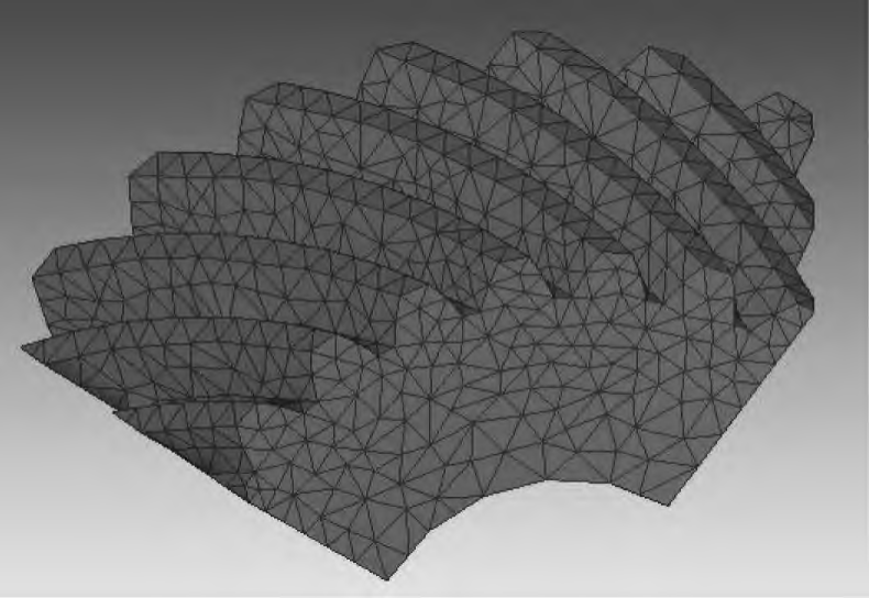
Figure 2 Helical bevel gear mesh model
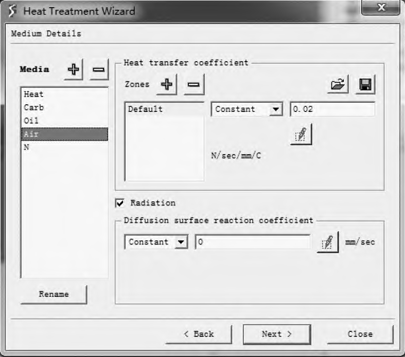
Figure 3 Air cooling definition interface
2.3 Residual stress extraction method for heat treatment
In order to be able to define the initial residual stress field of the grinding finite element analysis more accurately, the residual stress state of the heat treatment needs to be extracted. The residual stress extraction method of heat treatment is as follows:
( 1) The heat treatment results of the helical bevel gear are split in the direction perpendicular to the tooth length, and the cross-section is shown in Figure 6;
( 2) Taking the extraction of X-direction stress as an example, using the SV Distribution between Two Points function in DEFORM software post-processing, select two distances of 0 in the vertical direction of tooth length, that is, tooth depth. A point of 25mm, as the start and end points, as shown in Figure 7, and evenly divided into 25 parts between the two points to obtain 0. 01 mm intervals between the stress results at various points, save the stress results to a text document, and the X-direction stress follows
The depth change curve is shown in Figure 8;
(3) According to the content of step (2), save the stress results of the remaining five directions to the text document, and the residual stress extraction results of heat treatment are shown in Table 3;
( 4) According to the content of steps ( 1 ~ ( 3), extract the stress distribution state of the remaining four points on the tooth surface of the helical bevel gear, and then obtain the average stress of the five points, so as to obtain the distribution state of the residual stress of heat treatment.
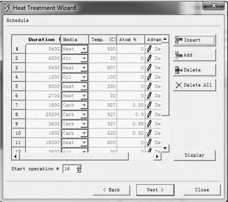
Figure 4 Heat treatment scheme definition interface
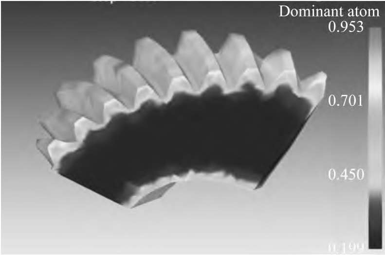
▲Figure 5 Analysis results of heat treatment of helical bevel gears
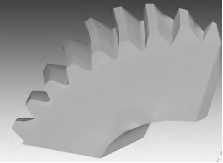
▲Figure 6 Cross-section of helical bevel gears along the tooth length
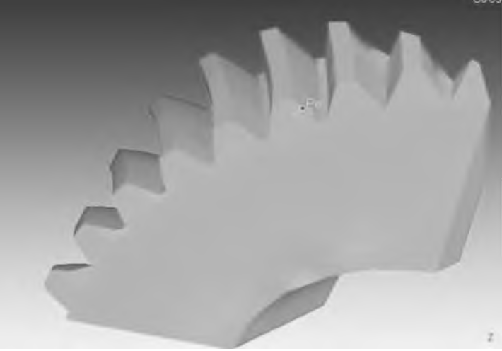
Figure 7 Start and end points
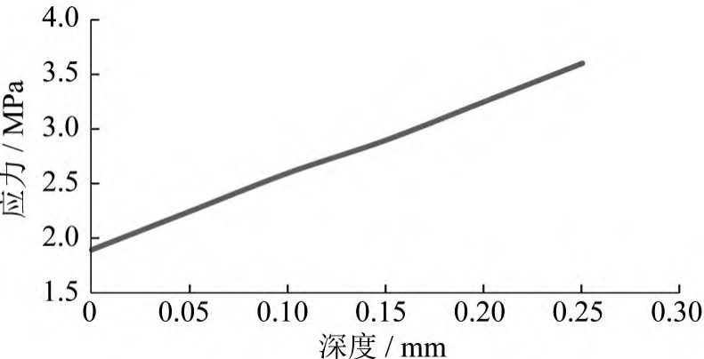
Figure 8 X direction stress change curve with depth
3 Helical bevel gear grinding simulation
3.1 Simulation model
1) Abrasive grain determination. The process of grinding the workpiece by abrasive grains is the process of elastic deformation to plastic deformation of the workpiece material under the action of abrasive particles, and until fracture. In the above process, the workpiece material is under the condition of high temperature, large strain and large strain rate, and thermoelastic plastic deformation is generated until ductile fracture failure occurs. In the study, it is assumed that the abrasive grain is a cone with a height of 180 μm, the top of the abrasive grain is partially worn. Due to the short ratio of time for grinding to reach steady state, grinding heat does not affect the entire workpiece, so only a part of the workpiece is modeled and meshed. According to the relevant literature, the change trend of the residual stress of the workpiece to the tooth surface below 200 μm is not obvious, so a small part of the area below the tooth surface 300 μm is selected as the workpiece model, and the workpiece model is selected
This is shown in Figure 9.
( 2) Meshing. The abrasive grain and the workpiece are meshed, and since the residual stress analysis of the workpiece is mainly carried out during the research process, the abrasive grain division adopts a tetrahedral mesh, which is a rigid body model. The workpiece is elastomeric, and for the accuracy of the calculation, a hexahedral mesh is selected. For simulation real In the grinding process, a virtual grinding wheel model based on the random distribution of multiple abrasive grains is established, and the abrasive grains are randomly distributed on the surface of the grinding wheel according to the grinding wheel particle size. The overall assembly model of the grinding wheel and workpiece is shown in Figure 10.
(3) Definition of contact friction relationship. When grinding, the grinding heat mainly comes from removing the shaping deformation of the material and the friction between the material and the tool. Define the abrasive grain as the active part, the helical bevel gear as the follower, the coulomb friction between the abrasive grain and the tooth surface, and the friction factor is 0. 2。
( 4) Material parameter setting. According to the properties of the abrasive, the grinding wheel can be divided into carbide grinding wheel, oxide grinding wheel, and superhard abrasive grinding wheel. During the analysis, cubic boron nitride is used for the sand material, and the main performance parameters are shown in the table4。 After the material parameters are defined, you need to assign the material parameters to the model. 5) Strain and failure model setting. In order to obtain the gear deformation and stress-strain states coupled with heat and stress strain during simulation, it is necessary to deline
The constitutive model of mechanical behavior of materials in large strain, wide strain rate range and wide temperature range is described. The Johnson-Cook model I use can It can meet the above working environment conditions of metal materials. In the Johnson-Cook model, the relationship between deformation parameters and temperature is: 5) Strain and failure model settings. In order to obtain the gear deformation and stress-strain state of thermal, stress-strain coupling during the simulation process, it is necessary to describe the constitutive model of the mechanical behavior of the material in the wide strain, wide strain rate range and wide temperature range. The Johnson-Cook model used by the author meets the above operating environment conditions for metallic materials. In the Johnson-Cook model, the relationship between deformation parameters and temperature is:
Table 3 Heat treatment residual stress extraction results
| 深度 | X 方向 | Y 方向 | Z 方向 | XY 方向 | XZ 方向 | YZ 方向 |
| 0 | - 4. 051 43 | - 1. 079 73 | - 6.600 93 | 12. 540 1 | - 13. 497 2 | - 11. 248 2 |
| 0. 010 417 | - 3. 861 76 | - 1. 119 38 | - 6. 744 62 | 12. 270 85 | - 13. 288 6 | - 11. 190 6 |
| 0. 020 833 | - 3. 668 28 | - 1. 161 67 | - 6. 889 46 | 11. 991 88 | - 13. 074 5 | - 11. 130 6 |
| 0. 031 25 | - 3. 474 8 | - 1. 203 96 | - 7. 034 31 | 11. 712 91 | - 12. 860 4 | - 11. 070 6 |
| 0. 041 667 | - 3. 281 32 | - 1. 246 24 | - 7. 179 15 | 11. 433 94 | - 12 646 3 | - 11. 010 5 |
| 0. 052 083 | - 3. 087 85 | - 1. 288 53 | - 7. 324 | 11. 154 97 | - 12. 432 1 | - 10. 950 5 |
| 0. 062 5 | - 2. 894 37 | - 1. 330 81 | - 7. 468 84 | 10. 876 | - 12. 218 | - 10. 890 5 |
| 0. 072 917 | - 2. 700 89 | - 1. 373 1 | - 7. 613 68 | 10. 597 04 | - 12. 003 9 | - 10. 830 5 |
| 0. 083 333 | - 2. 507 41 | - 1. 415 38 | - 7. 758 53 | 10. 318 07 | - 11. 789 8 | - 10. 770 5 |
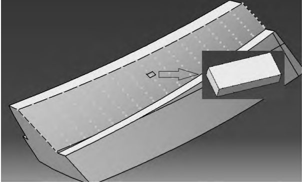
Figure 9 Workpiece model selection
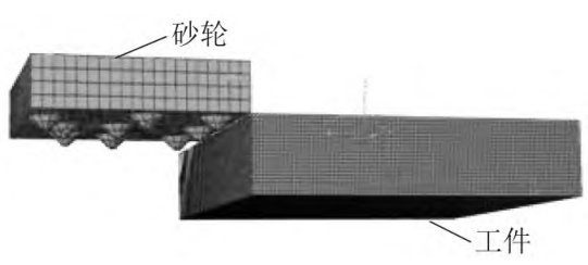
Figure 10 Grinding wheel and workpiece assembly model
Table 4 Cubic boron nitride performance parameters
| 项目 | 数值 |
| 热膨胀系数/( μm·m - 1·K - 1 ) | 2. 1 |
| 密度/( kg·m - 3 ) | 34 800 |
| 泊松比 | 0. 16 |
| 弹性模量/GPa | 720 |
| 热传导率/( W·m - 1·K - 1 ) | 1 300 |
| 比热容/( J·kg - 1·K - 1 ) | 612. 5 |
| 热膨胀系数/( μm·m - 1·K - 1 ) | 2. 3 |
Table 5 Johnson – Cook Model Parameters
| 项目 | 数值 |
| A /MPa | 507 |
| B /MPa 320 | 320 |
| n | 0. 28 |
| C | 0. 064 |
| m | 1. 06 |
In the actual machining process, the material will break due to the action of the tool and form grinding chips. In order to describe this phenomenon more accurately during simulation, the damage parameter ω was introduced to characterize the failure form of the material. When the damage parameters reach a certain value, the material breaks. Damage ginseng The number is: ω = ( ε—pl0 + ∑ Δε—pl/ε—plf (2): ε—pl0 is the initial equivalent plastic strain; Δε—pl is the equivalent plastic strain increment; ε—PLF is the equivalent breaking plastic strain of the reference temperature and strain rate. In ABAQUS software, the fracture of the material is characterized by entering the failure parameters d1 ~ d5. The failure parameters are shown in Table 6.
Table 6 Failure parameters
| 失效参数 | 数值 |
| d1 | 0. 1 |
| d2 | 0. 76 |
| d3 | 1. 57 |
| d4 | 0. 005 |
| d5 | - 1. 84 |
(6) Several hypotheses. When simulating the grinding of a single abrasive grain, the following assumptions are made: (1) The cubic boron nitride abrasive grain has been partially blunted, and there is friction on the bottom surface; (2) The workpiece material is defined as ideal thermoelasticplasticity
Body; (3) The friction factor between the abrasive grain and the workpiece is kept at a constant value, and does not change with the change of external conditions; (4) The size of the abrasive grain is much smaller than the size of the workpiece in macroscopic terms, and the time for the abrasive grain to act with the workpiece is very short, under such conditions, the grinding process is regarded as a separate abrasive grain Surface grinding.
(7) Initial stress field coupling of heat treatment. On the basis of grinding finite element simulation, the residual stress state of heat treatment is added as the initial stress field of grinding, so as to improve the initial conditions of grinding. Firstly, according to the residual stress extraction method of heat treatment, the stress fraction along the depth direction has been obtained
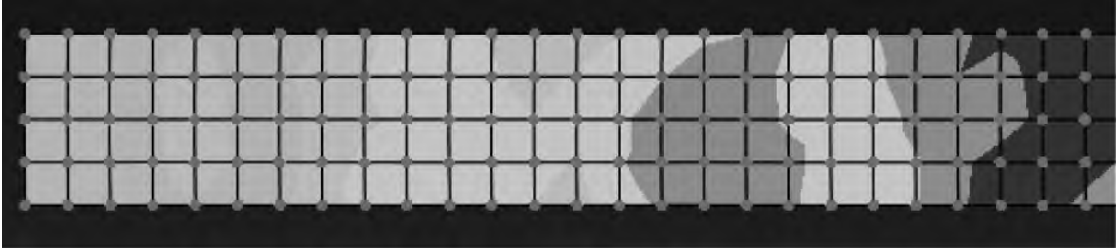
Cloth status result file. A collection of 25-layer elements is then built in the ABAQUS software along the grinding depth, as shown in Figure 11. Finally, through the predefined stress field variable settings, the stress states of the 25 points are entered into the 25-layer element set in turn, and the predefined stress field variable setting interface is shown in Figure 12.
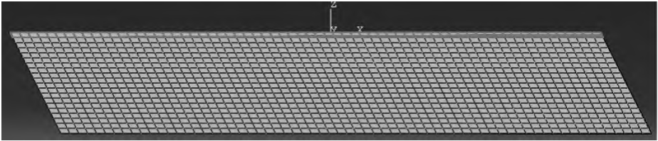
▲Figure 11 Collection of grinding depth direction elements
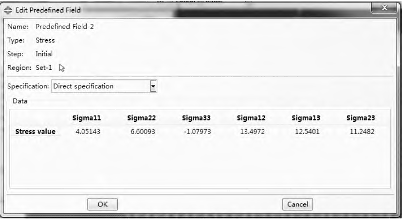
Figure 12 Predefined stress field variable setting interface
3.2 Extraction of simulation results
After building the simulation model based on the foregoing, submit the job file and obtain the single abrasive grinding process through the finite element analysis of the ABAQUS software, as shown in Figure 13.
▲Figure 13 Single abrasive grinding process
The stress extracted by the author’s analysis is S11 comprehensive stress, that is, the stress direction is consistent with the grinding direction in three-dimensional space. Using the Cartesian coordinate system of the system, in the result file of grinding simulation machining calculation, the edge area with relatively large error is ignored, and 515 nodes on the grinding path are selected as stress extraction nodes. The grinding residual stress extraction is shown in Figure 14. By averaging the 515 points, the average stress of the corresponding layer after grinding can be obtained.
▲Figure 14 Grinding residual stress extraction
3 .3Influence of grinding parameters on residual stress
The influence law of grinding speed, grinding depth and feed speed on grinding residual stress was studied, and the three-factor and five-level orthogonal tests were adopted, with a total of 25 groups. The maximum residual compressive stress was selected as the criterion for the test results, and the test results are shown in Table 7 and the test analysis is shown in Table 8. Among the three factors, the grinding depth of cut has the greatest effect on the maximum residual compressive stress, followed by grinding speed and the least influence of feed speed. In the actual grinding process, it is necessary to select according to the actual conditions and research results
Choose the right grinding depth and grinding speed, and then select the appropriate feed rate
degree, complete the grinding process. The following mainly analyzes the influence of grinding depth of cut and grinding speed on residual stress. Set the grinding speed to 15 m/s and the feed speed to 0. 04 m/s, respectively, simulated grinding depth of 0. 01 mm、0. 015 mm、0. 02 mm、0. Distribution of residual stress at 025 mm, as shown in Figure 15 along the grinding path. As can be seen from Figure 15, the maximum residual compressive stress occurs in the subsurface position, and the residual compressive stress in the inner layer gradually becomes the residual tensile stress. With the increase of grinding cutting depth, the maximum residual compressive stress increases, and the depth of residual compressive stress also increases slightly. Let the grinding depth of cut be 0. 02 mm with a feed rate of 0. 04 m/s simulates the distribution of residual stress at grinding speeds of 17 m/s, 20 m/s, 22 m/s, and 25 m/s, respectively, as shown in Figure 16 along the grinding path.
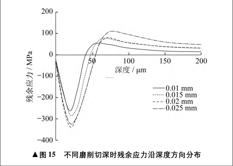
▲Figure 15 The residual stress is distributed in the depth direction during different grinding depth cuts
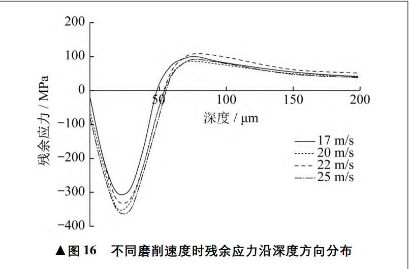
▲Figure 16 The residual stress is distributed in the depth direction at different grinding speeds
As can be seen from Figure 16, the maximum residual compressive stress occurs in the subsurface position, and the residual compressive stress in the inner layer gradually becomes the residual tensile stress. With the acceleration of grinding speed, the maximum residual compressive stress increases, and the residual compressive stress is of The depth of action does not increase significantly.
4 Test verification
4.1 Test equipment
The workpiece material is 12Cr2Ni4A steel, and the helical bevel gear processed is right-handed, the parameters are shown in Table 9. The X-ray stress tester used for the test is shown in Figure 17. The polishing equipment required for dissolution in the test is shown in Figure 18.
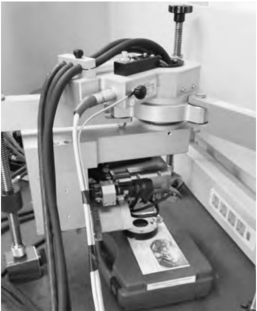
Figure 17 X-ray stress tester
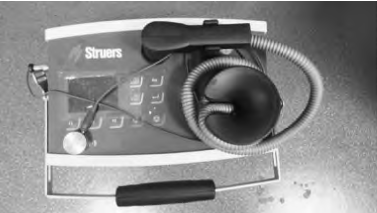
Figure 18 Polishing equipment
4.2 Test protocol
For gears tempered according to the heat treatment route, the grinding speed is 20 m/s and the grinding depth is 0. 02 mm、0. 03 mm The sample part is ground and the helical bevel gear is wire-cut, and the single-tooth sample is shown in Figure 19.
4.3 Residual stress test results
The residual stress was tested using the X-ray method to obtain 0, 20 μm, 40
Residual stress at μm, 60 μm, 80 μm, 100 μm depth, stress square
The direction is the tangential direction along the grinding wheel.
4.4 Data comparison
According to the results of the residual stress test of the two sets of tests, according to the correspondence between residual stress and depth, the trend chart of residual stress along the depth direction is drawn respectively, and then compared with the results obtained by finite element grinding simulation machining, as shown in Figure 20.By comparing the test results with the finite element simulation results, it is found that there is a difference in the approximate fixed value between the two values. During the test, for the processed helical bevel gear, different machining processes will have a certain impact on the stress state of the gear tooth surface. In simulation, it is only a single test
Residual stress effects caused by heat treatment processes. Therefore, there is a certain difference in the value between the two. Of course, the trend of surface residual stress in the depth direction after the helical bevel gear grinding process is consistent, that is, The influence of the simulated process parameters on the residual stress is valid and feasible For reference.
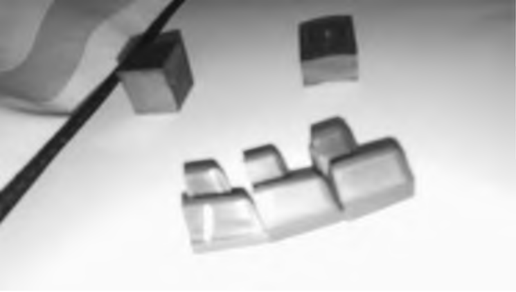
▲Figure 19 Single tooth sample
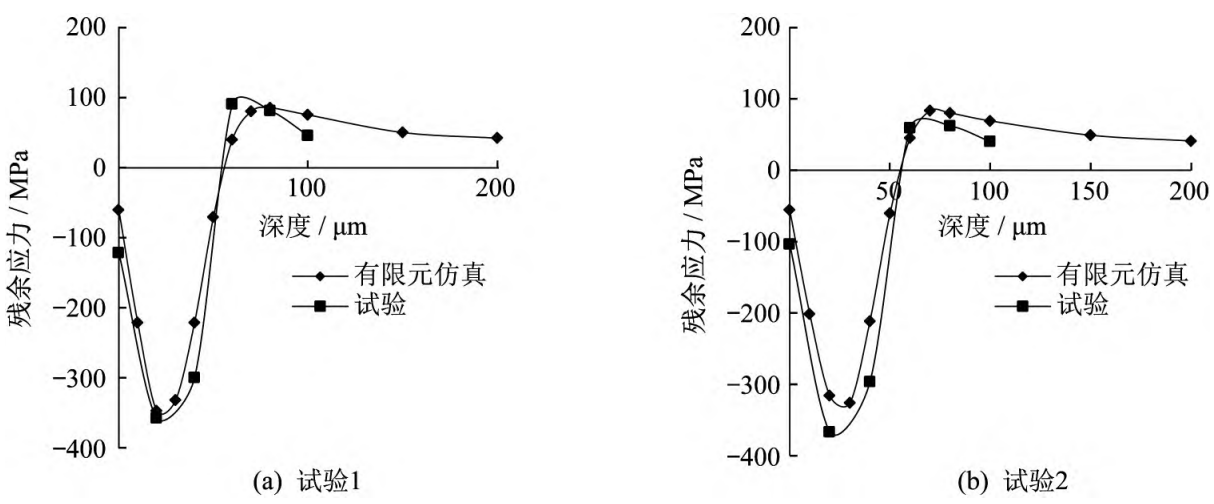
▲Figure 20 Comparison of residual stress
5 Concluding remarks
In this study, the author uses DEFORM finite element analysis software to establish a 12Cr2Ni4A steel helical bevel gear carburizing and quenching finite element analysis model, numerical simulation of helical bevel gear heat treatment, extracting the residual stress state of the tooth surface after heat treatment, and establishing a grinding finite element analysis model in ABAQUS software, coupling the residual stress field of the heat treatment process, analyzing the influence of different grinding parameters on the residual stress, and obtaining the grinding depth of cutting It is the factor that has the greatest influence on residual stress. At the same time, helical bevel gear heat treatment and grinding processing test verification are carried out, and the residual stress obtained by different grinding process parameters is tested Compare and analyze the simulation results and test results to verify the finite element simulation The reliability of the obtained data and the credibility of the obtained rules.