
0 Introduction
Hypoid gears have the characteristics of large degree of overlap and stable transmission, and are widely used in vehicle drive axle transmission. Due to the complex tooth surface, the adjustment of machine tool processing parameters is cumbersome, and its meshing performance control is more difficult. The tooth surface meshing contact zone is related to the meshing performance of the teeth such as vibration, noise and smooth operation. Due to the existence of processing error and installation error, there is a deviation between the actual tooth surface and the theoretical tooth surface. According to reality The contact impression roll test results of the machining tooth surface, adjusting the position of the contact zone, and then correcting the processing parameters are the key links in the meshing performance control of hypoid gears. Therefore, the tooth surface is accurately fitted according to the measurement results of the actual tooth surface for meshing performance Analysis is the premise of the calculation of tooth surface machining parameter adjustment. Aiming at the discrete measurement data of the real tooth surface of hypoid gear, Li Gang et al. used the block interpolation method to construct the digital tooth surface, which improved the fitting accuracy of the tooth surface Degree. Zhang Junhui et al. performed bicubic NURBS surface fitting on the measurement data of the tooth surface of the arc bevel gear, and carried out contact analysis, and the contact imprint was consistent with the actual roll check results. Du Jinfu et al. are based on cycloids The measured data of the tooth surface of the bevel gear is used to fit the real tooth surface by digital tooth surface, and the tooth surface contact analysis is carried out, which comprehensively reflects the meshing information of the actual tooth surface. Wang Zhonghou et al. proposed a calculation method for real tooth surface unloaded contact spots, which truly reflected the tooth surface meshing Information such as contact trajectories and contact marks in the process.
Based on the measurement results of the actual machined tooth flank point of the hypoid gear, this paper uses the fitting method of bicubic NURBS surface to compare the actual teeth The surface was reconstructed, and the transmission error and meshing imprint of the real tooth surface were obtained by using the discrete tooth surface contact analysis method, and the hypoboloid tooth was obtained The quality evaluation of wheel processing and the correction of processing parameters provide a basis.
1 Actual tooth surface fitting
According to the actual tooth surface measurement results of hypoid gears, the deviation value δij of the tooth surface measurement point is superimposed with the three-dimensional coordinates of the theoretical tooth surface point to obtain the coordinates of the real tooth surface point

In the formula, I and j are the tooth surface grid points in the tooth height direction and the tooth length direction, respectively. Ri,j,RI,j are the grid point position vectors of the actual and theoretical tooth surfaces, respectively. ni,j is the unit-method vector of theoretical tooth surface mesh points. For real-world contact analysis, double and triple times were used NURBS surface construction method, which reconstructs the actual tooth flank of the hyperid gear. The expression for reconstructing the tooth flank is
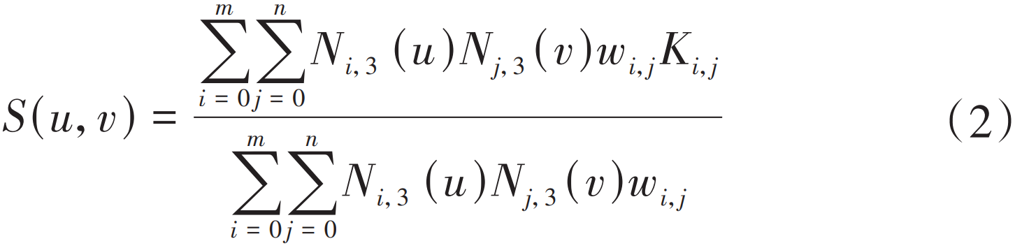
where Ki,j are the control points of the reconstructed tooth surface; i, j are the number of control points, there are (m + 1) × (n + 1) number; wi,j is the corresponding weight factor; Ni,3,Nj,3 are B-spline basis functions in the u-direction (tooth length) and v-direction (tooth height), respectively. According to the measurement results of the tooth surface mesh point, the control points of the NURBS curve are calculated in the tooth height direction of the actual tooth surface, and then all the control points of the tooth surface are calculated in the tooth length direction to obtain the reconstructed real tooth surface.
According to the tooth surface measurement standard, the number of tooth surface mesh points detected on the gear measuring center is (5×9). In the tooth surface contact analysis, in order to obtain the accurate position of the tooth surface meshing point, it is necessary to rely on accuracy
Requires interpolated encryption of control points. As shown in Figure 1, 45 control grid points can be interpolated by bicubic splines to obtain encrypted grid points.

Figure 1 Tooth surface interpolation encryption
2 Installation distance adjustment calculation model
Contact marks on the actual tooth surface generally deviate from the preset position
as shown in Figure 2. M* and M0 are actual and ideal contact bits, respectively
Let M* deviate from M0 at a distance coordinate of (s,t). In the coordinate system (O0X0, Y0), the M* coordinate is (x∗2,y∗2), the point has the following relationship with the three-dimensional tooth plane coordinates (x2,y2,z2) of M0 in the coordinate system (O2:X2,Y2,Z2):
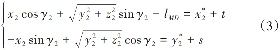
where γ2 is the cone angle of the large wheel; lMD is the midpoint of the large tooth surface
Cone pitch.
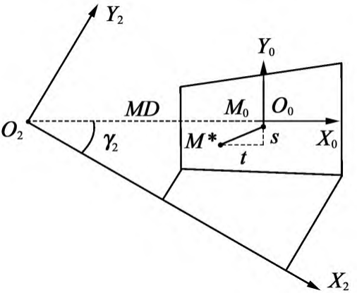
Figure 2 Position of the tooth surface meshing point
In order to obtain the correction of the processing parameters of the actual tooth surface, it is first necessary to adjust the position of the meshing point, obtain the adjustment amount of the large wheel installation distance, small wheel installation distance and offset distance when the contact point is M0, and then convert it into the actual one Machine tool machining correction value. Based on the bevel gear rolling method, the tooth surface meshing relationship between large and small wheels is established, as shown in Figure 3.
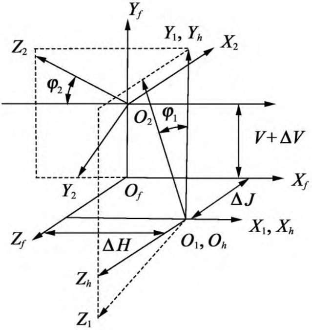
Figure 3 Tooth surface meshing relationship
In Figure 3, (Of:Xf,Yf,Zf) is a fixed coordinate system; (O1:X1,Y1,Z1) and (O2:X2,Y2,Z2) are the follow-up coordinate systems solidly connected to the small and large wheels, respectively; ΔV, ΔH, and ΔJ are all contact impression position adjustment quantities; V is the offset distance. In a fixed coordinate system, the meshing of the tooth surface of large and small wheels needs to satisfy the following relationship:
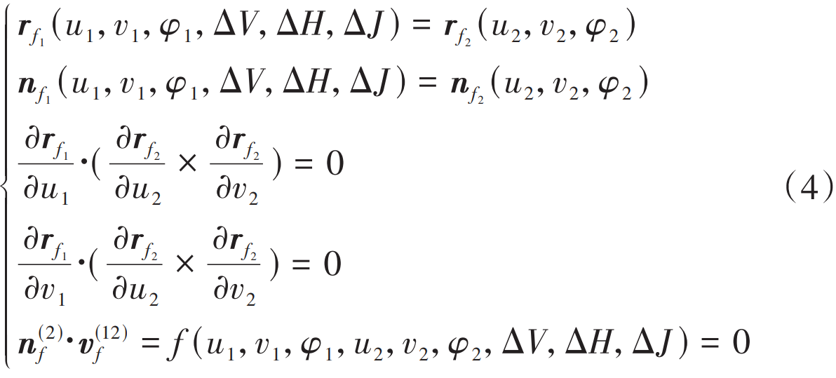
where rf is the meshing point position vector; nf is the meshing point unit legal vector; φ meshing angle for gears; u and v are both tooth surface parameters; The subscripts 1 and 2 indicate small and large wheels respectively; v(12)f is the relative velocity of the large and small wheels at the meshing point. Contact imprint position adjustment process is required Keep the tooth side clearance constant, satisfying the following relationship:

where γ1 is the cone angle of the small knot.
Equation (4) and Equation (5) contain multiple equations, each using fd (X)
(d=1,2,…,9) denotes that the solver quantity u1,v1,φ1,u2,v2,φ2, ΔV, ΔH, ΔJ are denoted by X. Since the measured tooth surface equation of the gear is connected by segmented cubic spline surfaces, conventional nonlinear solution methods are difficult to solve. Uses the Newton-Raphson iteration algorithm, respectively, the 9 variables of the equation system fd are deflected to the 1st order, which can be grouped Jacobi matrix F'(Xk) into 9×9d )。 Indicates the number of iterations in k The solution of the final system of equations is

After a loop iteratively calculates, when ||Xk + 1 – Xk|| < σ (σ is the solution accuracy), Xk + 1 is the solution of the system of equations, that is, the tooth plane coordinates of the meshing location. When performing tooth surface contact analysis, this position is used as the initial iteration point, and the other solutions are solved by constantly changing the rotation angles of large and small wheels, thus forming a meshing trace of the tooth surface.
3 Analysis of actual tooth surface contact performance
The hypoid gear pair is point contact meshing, at the meshing point position, the tooth surface distance of the large wheel and the small wheel is 0, and the tooth surface distance along the tooth length direction and the tooth height direction gradually increases, when the tooth surface grid point is dense enough, by solving the spatial distance between all discrete points in the meshing area, the minimum value is approximately equal to the tooth surface distance. Pij2 represents the point on the large wheel tooth surface rf2, Pij1 represents the point on the small wheel tooth surface rf1, then, Pij 2 and Pij The spatial distance between 1 is

If the density of the tooth surface points meets the solution accuracy requirements, the position of the tooth surface meshing point can be determined by calculating the minimum distance min (Dp × q).
3.1 Tooth surface two-dimensional golden section encryption
Among the optimization algorithms, the golden section algorithm is simple, converges quickly, and has significant effects, which is the basis of many optimization algorithms. The two-dimensional golden section method is based on the one-dimensional algorithm, and the feasible planar rectangular area is divided into 0 in the two-dimensional direction. The proportions of 618 and 0. 382 are divided, and then the function value at the center of each small rectangle after the split is compared, and the rectangular area where the smallest function value is located continues to be divided until the size of the rectangular area is less than the given precision. The convergence of the two-dimensional golden section has been mathematically rigorously proven. Firstly, the initial meshing point position of the large and small wheels is calculated, and then according to the solution accuracy, the area near the meshing point is encrypted twice or more times for the two-dimensional golden section, and the meshing point that meets the accuracy requirements is found for different gear rotation angles. The tooth surface encryption process is shown in Figure 4.
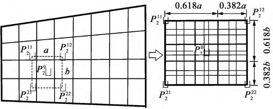
Figure 4 Two-dimensional golden section on tooth flank
3.2 Tooth surface meshing interference judgment
The meshing state of the tooth surface point is judged by whether the two tooth surfaces interfere, that is, the large wheel tooth surface Pij2 point and the small wheel tooth surface Pij The difference vector between 1 pip and Pij Whether the inner product between the vectors at point 1 is less than 0 is denoted as

If min (Sp × q) < 0, then meshing interference occurs on the tooth surfaces of large and small wheels. The calculation flow of tooth surface meshing analysis is shown in Figure 5.
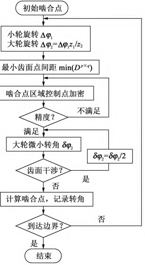
Figure 5 Actual tooth surface meshing solution process
4 Example analysis
According to the calculation process shown in Figure 5, a hypoid axle of a vehicle axle is calculated and solved. The basic parameters of the gear pair are shown in Table 1, and the measurement results of the tooth flanks of small and large wheels are shown in Figure 6. According to the tooth surface meshing analysis solution process shown in Figure 5, the actual is obtained
The transmission error curve and contact imprint of the tooth surface are shown in Figure 7(a). The contact imprint on the convex surface of the large wheel is biased towards the big end. According to the position of the contact imprint, the adjustment amount of the imprint is roughly as follows: the moving distance t in the small end direction is 7 mm, and the moving distance s in the tooth top direction is 1 mm. Using equation (6) to solve for the solution, the adjustment quantities of ΔV, ΔH and ΔJ are 0. 312 mm、-0. 433 mm and 0. 062 mm, the adjusted tooth surface contact analysis results are shown in Figure 7(b). The adjustment amount can be converted into the corresponding machine tool processing parameter correction amount, such as tool position, wheel position correction, etc., the purpose of the tooth surface roll check is to verify whether the position and shape of the actual tooth surface contact imprint meet the expected design requirements. In order to verify the correctness of the algorithm, the processing parameter adjustments were compared on the CNC roll checking machine The results of the contact impression roll check before and after, as shown in Figure 8. Figure 8(b). The contact imprint of the actual large wheel convex surface is shown, which is consistent with the results of the simulation analysis. Figure 8(c) shows the position of the tooth surface contact zone after the processing parameters of the concave surface of the small wheel, and the contact zone is moved from the large end of the convex surface of the large wheel to the position close to the midpoint of the tooth surface, and the theoretical analysis and the actual processing roll check knot The correctness of the model built in this paper is verified.
Table 1 Basic parameters of hypoid gear pairs
| 参数 | 小轮 | 大轮 |
| 齿数 | 8 | 39 |
| 模数/mm | 4.611 | 4.611 |
| 齿面宽/mm | 25 | 25 |
| 偏置距/mm | 25 | 25 |
| 外径/mm | 56.73 | 171.05 |
| 螺旋角 | 50° | 30°41′ |
| 节锥角 | 14°11′ | 76°49′ |
| 面锥角 | 18°10′ | 77°43′ |
| 根锥角 | 11°37′ | 70°48′ |
| 螺旋方向 | 左旋 | 右旋 |
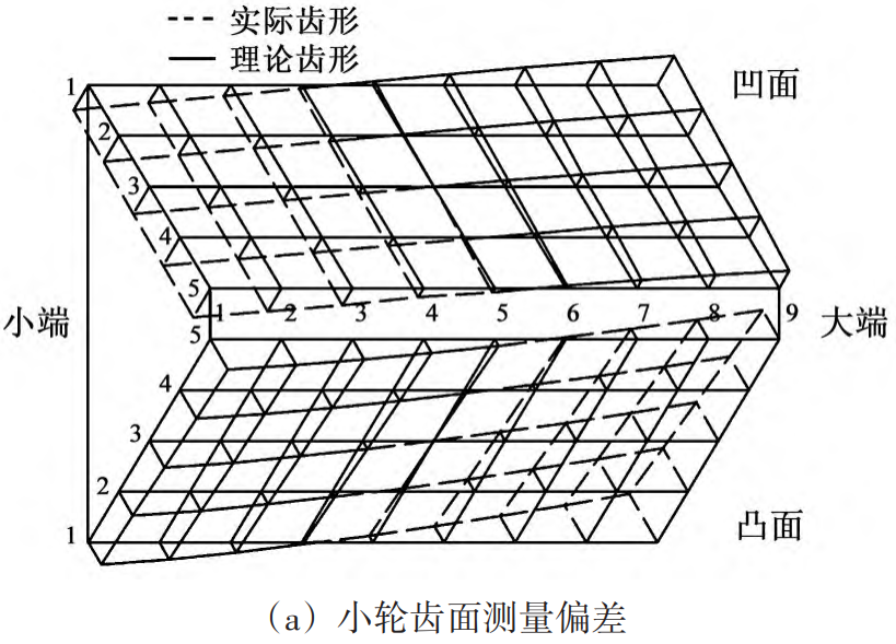
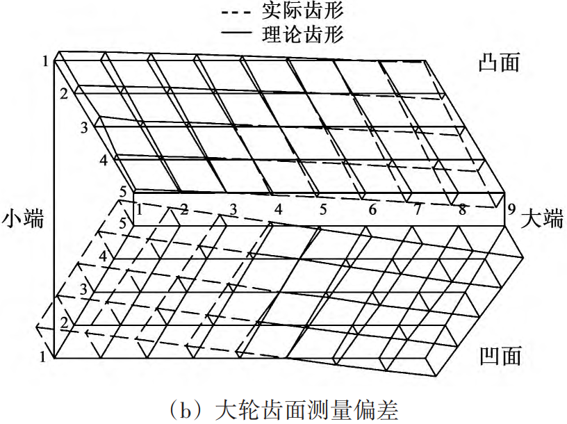
Fig. 6 Measurement results of tooth surface deviation
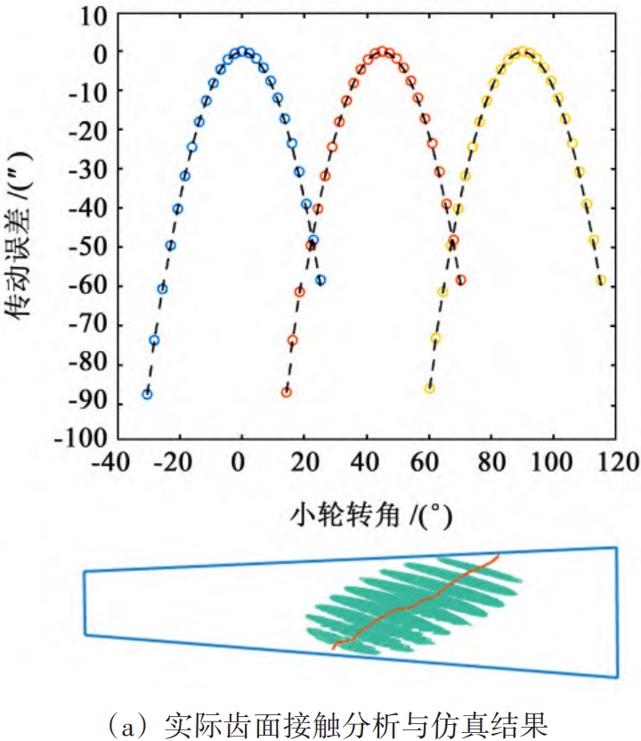
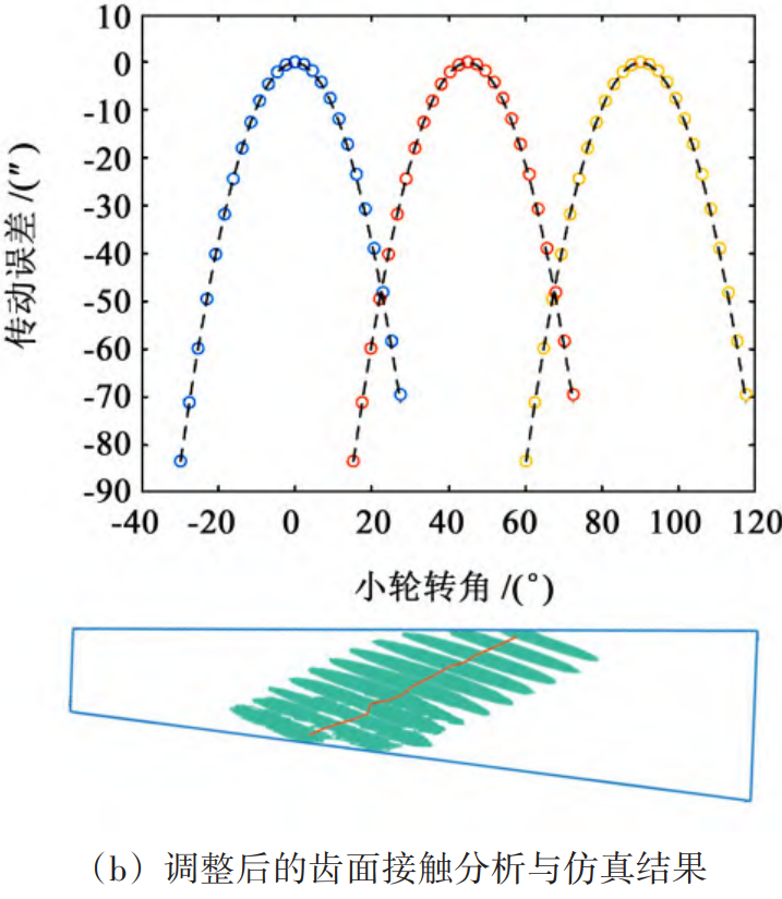
Fig.7. Tooth surface contact analysis and simulation results

5 Conclusion
(1) Based on the actual tooth surface measurement results of hypoid gears, the tooth flanks of large and small wheels were reconstructed by using bicubic NURBS surfaces. Based on the two-dimensional tooth surface golden section encryption method, the actual is compiled The contact performance analysis algorithm of the tooth surface can quickly solve the tooth surface meshing trajectory and avoid the cumbersome solution of nonlinear equations.
(2) The meshing performance analysis algorithm using the actual tooth surface can replace the traditional roll test test, and the corresponding tooth surface processing parameters can be inversely corrected by adjusting the calculation results through the contact area.
(3) Taking a hypoid gear pair of a axle as an example, the roll check verification is carried out, which shows that the contact imprint of the actual tooth surface is basically consistent with the actual roll test result, which verifies the correctness of the actual tooth surface meshing analysis algorithm.