0 Introduction
The gear-rotor system is one of the commonly used motion and power transmission mechanisms in industry. As the requirements of modern industry for gear drive systems evolve towards heavy-duty, high-speed and demanding working environments, gears are more prone to failure. In gear and its transmission system failures, the proportion of tooth root cracks is almost 40% of all faults. When a failure occurs, it can cause system downtime at best, or cause significant economic losses or even people
casualties. Therefore, root crack faults in various gear systems must be able to be accurately detected, controlled and tracked. The time-varying nature of meshing stiffness can reflect various factors that affect the meshing condition of gears, and the Finite Element Method (FEM) is an effective tool for calculating time-varying meshing stiffness, but the calculation amount is large, and the meshing and post-processing process are complex. The energy method has high efficiency and is still the mainstream method for calculating time-varying meshing stiffness.
In 2011, Chen et al. proposed for the first time a crack model in which cracks propagate along tooth width and tooth thickness. Verma et al. determined the crack growth path of spur cylindrical gear by the Extended Finite Element Method (XFEM), and studied the gear crack of the wheel flange thickness
The effect of the grain expansion path. Based on computer simulation, Feng Nana et al. proposed a new analytical algorithm to quantify the time-varying meshing stiffness of meshing gears under different fault conditions. Sun Guangyao et al. [8] considered the initial parameters of different cracks and used finite element software to explore the distribution of numerical curves including three-dimensional crack helical gear stress intensity factor and J integral. Wang Jinwen et al. considered that the base circle and the tooth root circle did not coincide, and used the improved energy method to calculate the influence of solar wheel crack failure on the meshing stiffness. Ning et al. proposed a non-uniform distribution of tooth root crack dynamics model based on the “slice method”, which revealed the dynamic characteristics of the gear transmission system with non-uniform distribution of cracks. Wan Zhiguo et al. compared and analyzed the analytical calculation model and internal mechanism of two faults, tooth root crack and tooth surface peeling, and analyzed the difference between the vibration response characteristics of the two faults through dynamic simulation. Xie Fuqi et al. comprehensively considered the time-varying meshing stiffness, dynamic error and other nonlinear excitations, and analyzed the influence of tooth root cracks along the tooth thickness penetration on the dynamic characteristics of the system. Liu Qikun et al. considered the characteristics of discontinuity and singularity of the actual crack tip, improved the XFEM and verified the accuracy and effectiveness of the model. Lai Junjie et al. Based on the full tooth energy equation, a bilateral asymmetric root crack model was established, and the calculation formula of meshing stiffness was derived. Zhang et al. synthesized the advantages of finite element method, Hertz contact theory and slice method, and proposed a new time-varying meshing stiffness calculation method for spur gear and helical gear pairs. Yang et al. re-evaluated the effective compression section and neutral layer of the crack gear considering the crack opening state, and further studied the differences between the proposed model and the traditional model in terms of meshing stiffness and dynamic response. Zhao et al. [17] used the coordinated deformation condition to derive the presence of cracks
Based on the Elas⁃to-Hydrodynamic Lubrication (EHL) model, the influence of root cracks on the tribological characteristics of tooth surfaces was obtained, and the tribodynamic behavior of gears under root cracks was studied. In general, most of the existing literature focuses on the crack growth path and system response of gear system at a specific crack level, and there are few studies on the modeling and calculation principle analysis of fault gear teeth at different crack levels. And the tooth root transition curve of the cracked gear teeth is usually The arc is approximately replaced, and the effective tooth thickness reduction limit line is a straight line parallel to the middle line of the gear tooth, which is still a certain gap from the real situation. In addition, the start point of the gear involute profile and the intersection point of the involute and the base circle do not coincide. None of the above literature mentions this.
Based on the previous research, this paper improves the calculation formula of time-varying meshing stiffness of large tooth number gears based on energy method from the geometry of cutting teeth and the principle of gear meshing. Introduce the transition curve parametric square Considering the more realistic effective tooth thickness reduction limit line, the fault gear tooth model with different crack levels is comprehensively established; The influence of gear tooth model correction, different crack degrees, and the specific form of effective tooth thickness reduction limit line on the calculation of cracked gear meshing stiffness is analyzed, and relevant suggestions for effective tooth thickness reduction limit lines with different crack degrees are given. By comparing with the results of the finite element method, the effectiveness of the proposed method is verified.
1 Improved method for calculating time-varying meshing stiffness of large tooth number gears
1.1 Rationale
The establishment of a planar Cartesian coordinate system is shown in Figure 1. In this paper, the gear teeth machined by rack tools are taken as the research object, and the transition curve is the equidistant line of the long involute line, and the parameter equation is:
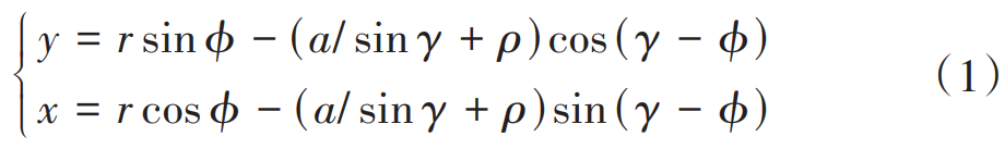
where γ ∈ (α0,π/2) is a variable parameter; r is the half-diameter of the fractional circle;
ϕ = (a/ tan γ + b)/r; a = h*am + cm – ρ is the corner circle of the top of the knife the distance between the center and the midline of the teeth; b = πm/4 + ham tan α0 +ρ cos α0 is the distance from the center of the corner of the top of the tool to the center line of the tool cogging; m is the modulus; α0 is the pressure angle; h*a、c Tooth top height coefficient and top clearance coefficient respectively; ρ = c*m/ (1 – sin α0) is the corner radius of the tool top. In Figure 1, point G, point H, and point Gb are the starting point of the involute tooth profile, the starting point of the transition curve tooth profile, and the intersection of the involute tooth profile and the base circle, respectively. The radius of the circle where the defined point is located is rG for the starting circle of the involute tooth profile, the radius rf of the root circle rf, and the radius rb of the base circle are as follows:
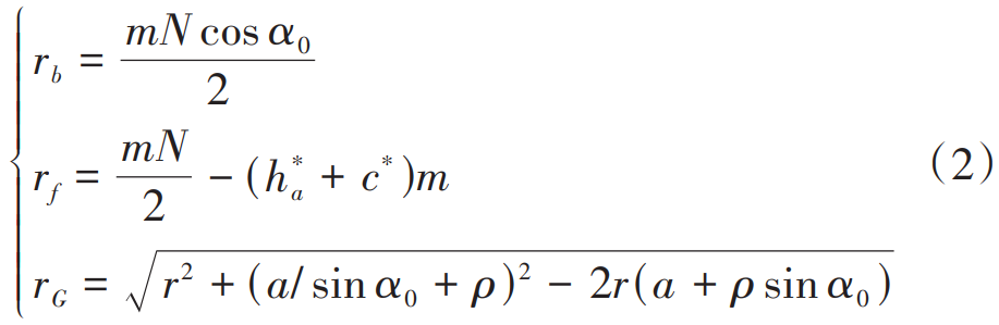
where N is the number of teeth; For standard involute cylindrical spur gears, this is obtained from equation (2) when the number of teeth is equal to 41. At 25, rb=rf. This article defines gears with a tooth count greater than 41 as large tooth count gears. The traditional potential energy Falun tooth model is shown in Figure 1(a), which has the following problems:
1) Only the relationship between the base circle rb and the root circle rf is considered. The starting point of the involute tooth profile and the base circle intersection point Gb ignores the objective fact that point G and point Gb are not the same point95.
2) In the gear tooth model, the base circle is always outside the root circle. In fact, when the number of teeth is large, the base circle is located inside the root circle. As shown in Figure 1(b), according to the assumptions of the traditional potential energy method, the transition curve will extend from point Gb to point H in the opposite direction, contrary to the objective facts. Combined with the cutting geometry and gear meshing principle 96-103, at this time, the radius of the circle opposite the starting point G of the involute tooth profile has changed from rb to rG, and the pressure angle has changed from α2 to αG. The difference between point G and point Gb is evident from Figure 1(b).
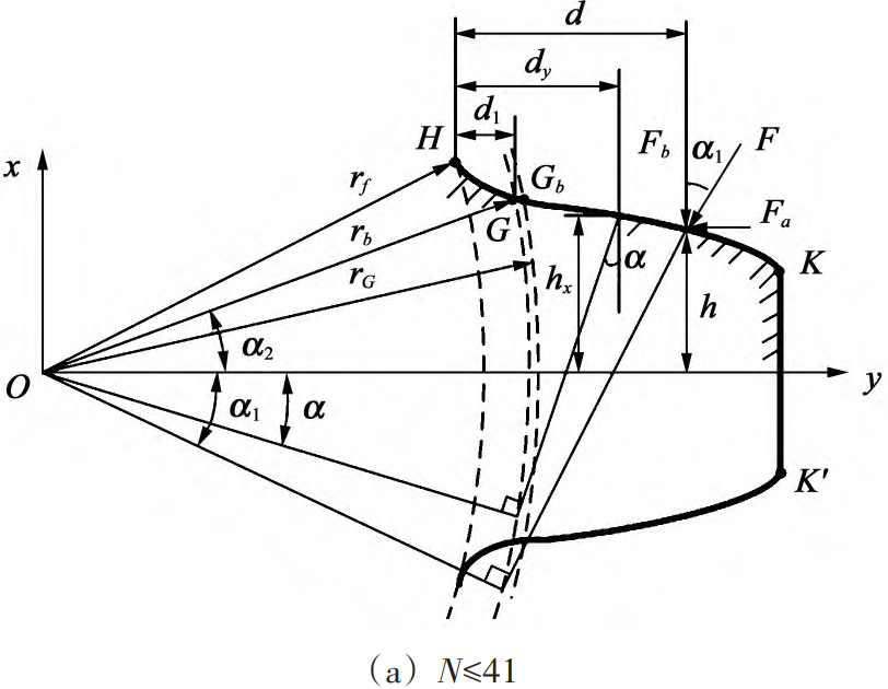
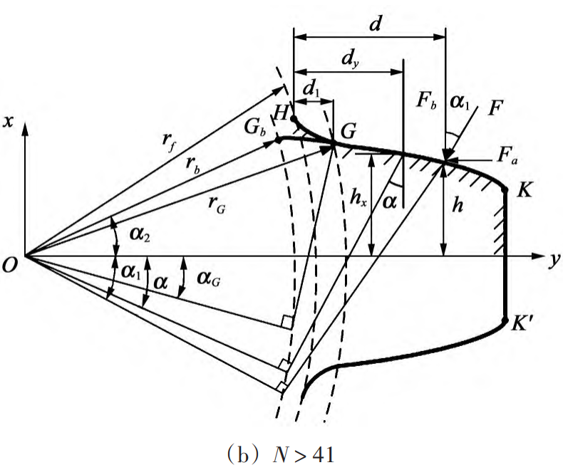
Fig. 1 Schematic diagram of the traditional gear tooth model and the modified rear gear tooth model
To solve the above problems, the key is to correctly distinguish the starting point G of the involute tooth profile and the intersection point Gb of the involute tooth profile and the base circle, and modify the traditional potential energy method according to the characteristics of the gear tooth profile with a large number of teeth.
1.2 Time-varying meshing stiffness improvement algorithm
The results show that the total potential energy of the meshing gear pair consists of 5 components, corresponding to Hertz contact stiffness kh, bending stiffness kb, shear stiffness ks, axial compressive stiffness ka, and tooth base stiffness kf. The kh and kf equations are respectively
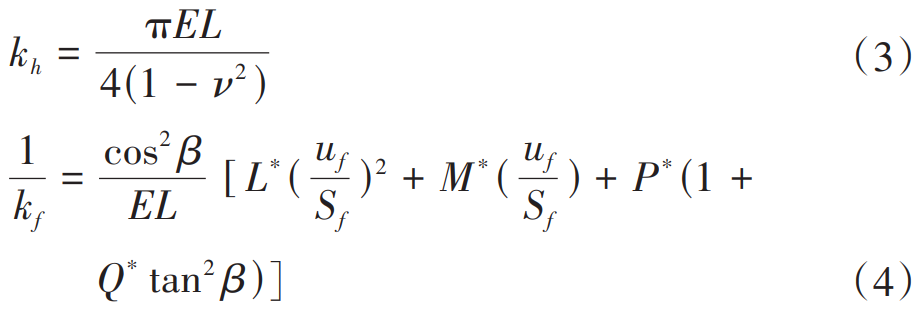
The meaning of each parameter in the formula is detailed in the literature [20], and will not be repeated in this article. From the knowledge of mechanics, you can obtain:
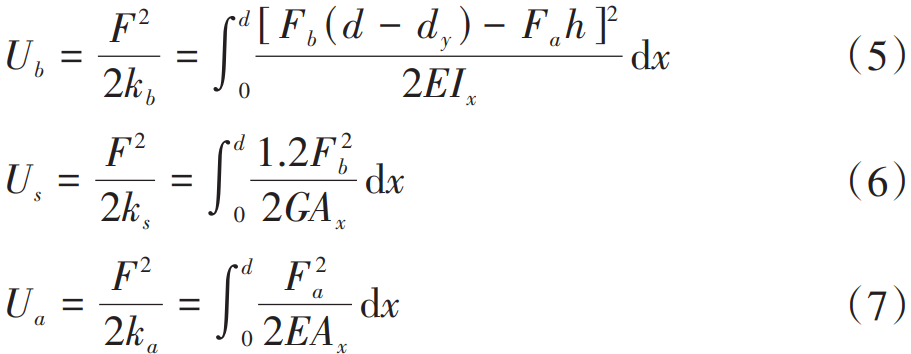
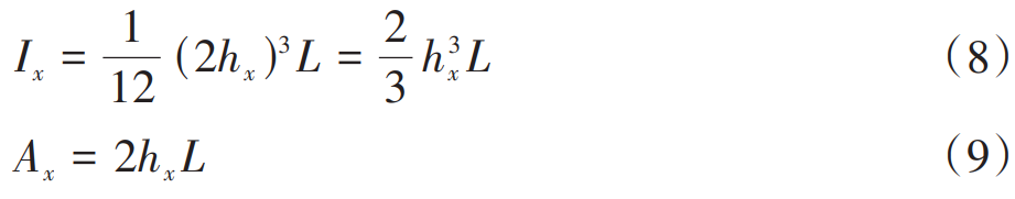
In the formula, d, dy, and d1 are the horizontal distances from any point on the meshing force action point, involute tooth profile and root transition curve to point H at the root circle; h = rb (α1 + α2) cos α1 – rb sin α1 is the vertical distance from the point of action of the meshing force to the point H; G is the shear modulus; E is the modulus of elasticity; L is the tooth width; ν is the Poisson’s ratio; Ix and Ax are the moment of inertia and the effective cross-sectional area of the gear tooth section at the distance from the root circle, respectively
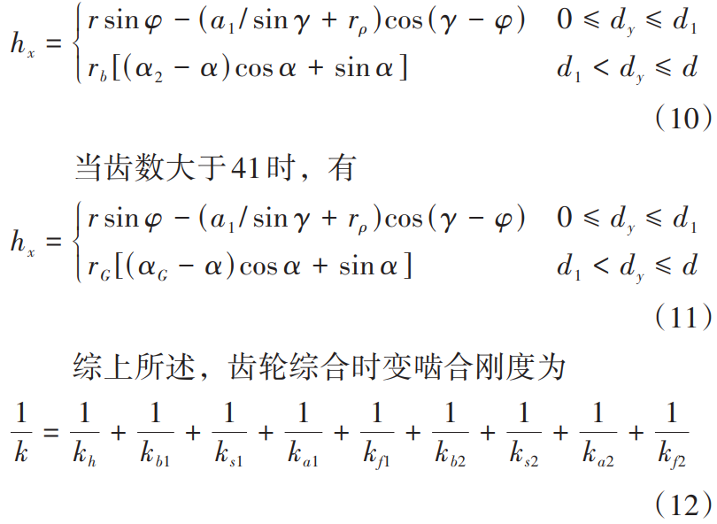
As mentioned earlier, when the number of teeth of the meshing gear is not greater than 41, the radius corresponding to the G point is rb and the pressure angle is α2; When the number of teeth is greater than 41, the radius corresponding to the G point is rG, and the pressure angle changes from α2
Combined (1) and involute geometric characteristics, when the number of teeth is not greater than 41, there is
2.1 Calculation model of meshing stiffness with different crack degrees
According to the literature [22], root cracks do not affect the integrity of tooth profile curve and effective tooth width, but only bending stiffness kb and shear stiffness Degree ks. This paper assumes that the crack appears at point H and that the crack runs through the full tooth and The angle to the midline of the teeth is υ. As shown in Figure 2, the crack model can be followed The degree of crack propagation is divided into the following four situations:
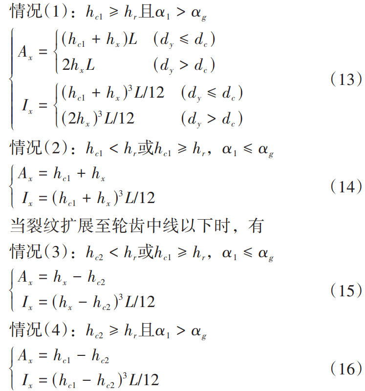
where hc1 = rf sin θH – q1 sin υ; hc2 = q2 sin υ。 H ( yH,xH ) can be found by equation (1), θH = arctan ( xH /yH ); hx see (11);The meaning of the other parameters is described above.
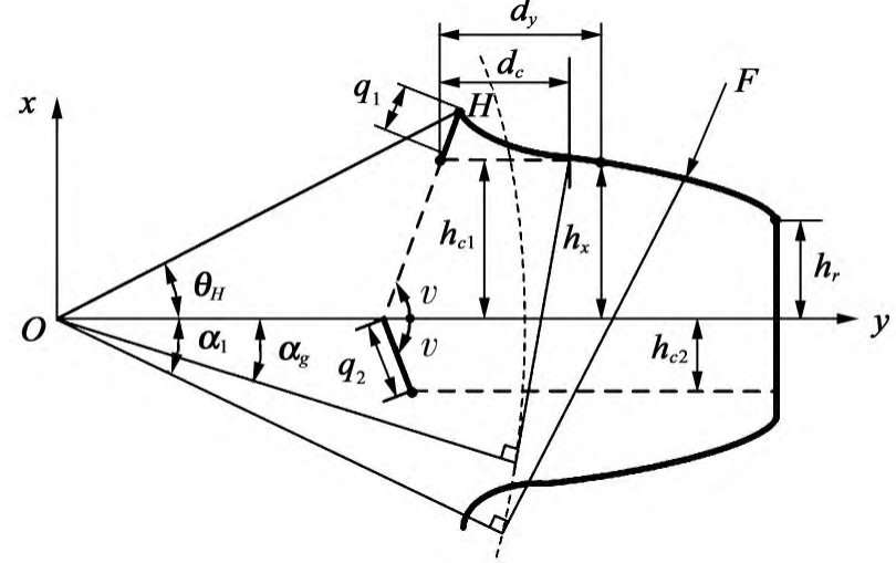
Figure 2 Linear cutting limit line crack gear tooth model
2.2 Further modification of the effective tooth thickness reduction limit line
The presence of root cracks will lead to a decrease in the effective tooth thickness, and the effective tooth thickness reduction limit line is defined as “Deadline”, tooth tooth The thick failure zone is called the “Dead zone,” as shown in Figure 3. In the first In section 1, the effective tooth thickness reduction limit line is assumed to be a straight line past the crack tip and parallel to the midline of the tooth. Mohammed et al. found that when the crack exceeds 30% of the tooth thickness, the meshing stiffness obtained by this line reduction has a large deviation from the calculation results of the finite element method, so he proposed to replace the straight line with a parabola as the limiting line, and verified the effectiveness of the method through FEM simulation and experiments.
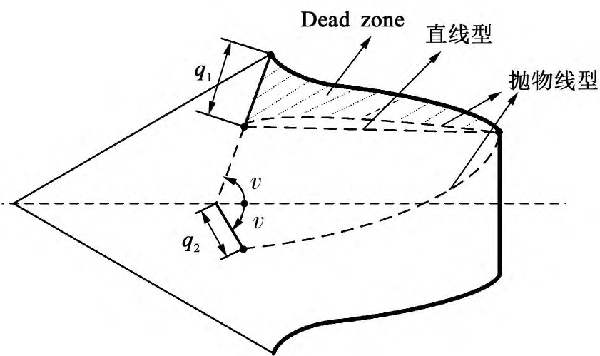
Fig. 3 Schematic diagram of effective tooth thickness reduction limit lines in different forms
The “parabolic type” effective tooth thickness reduction limit line is closer to the real situation, but there are problems such as modeling difficulties and complex calculations. Consider that in the actual calculation, the stress distribution gradient can be fitted in combination with the finite element method
On the basis of the modified gear tooth model, according to the stress gradient distribution of meshing gear teeth under load[24]461-468, the oblique line connecting the crack tip point A and the crack side tooth point K are used instead of straight lines as the effective tooth thickness reduction limit line. The crack gear tooth model is shown in Figure 4. At this time, crack growth is divided into the following two forms:
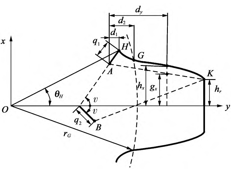
Fig.4. Slash reduction limit line crack gear tooth model
3 Calculation results and analysis of gear meshing stiffness
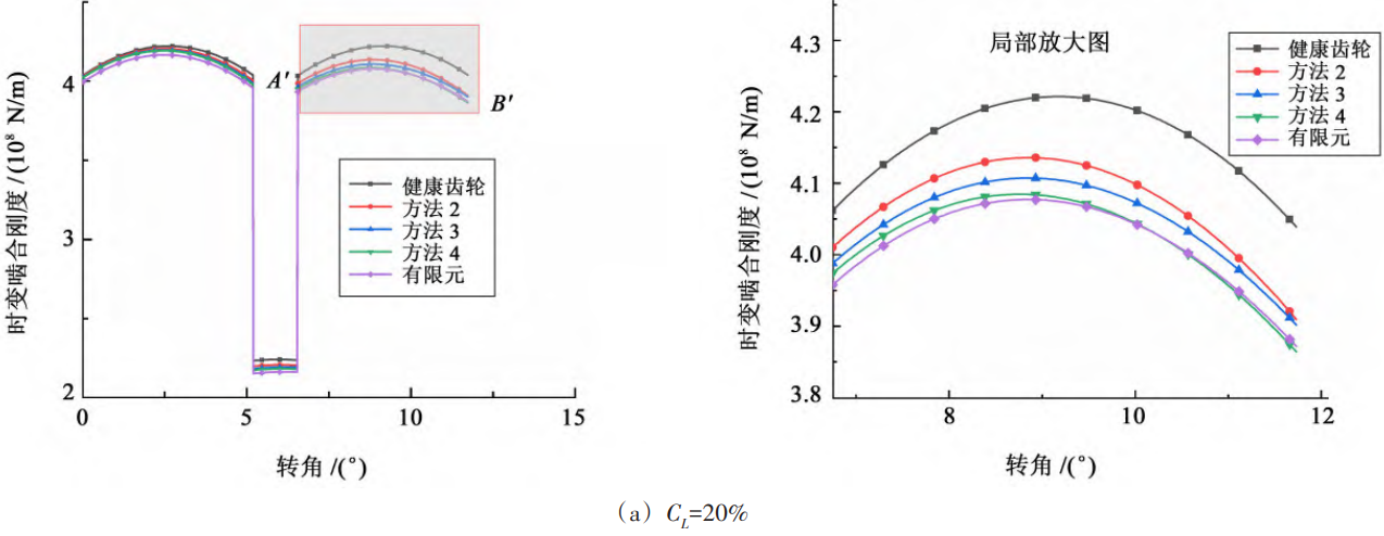
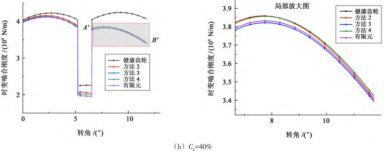
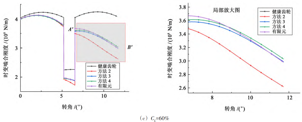
As can be seen from Figure 5, the stiffness of the latter meshing cycle decreases more than the previous meshing cycle in the two-tooth meshing region. This is because the effective contact length of the cracked gear teeth increases during the process of moving from the tooth root to the tooth top, resulting in the proportion of bending stiffness and shear stiffness of the cracked gear teeth in the comprehensive meshing stiffness, which makes the crack effect more prominent.
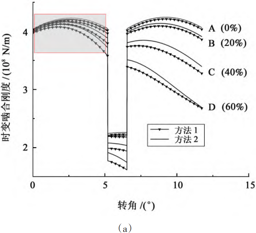
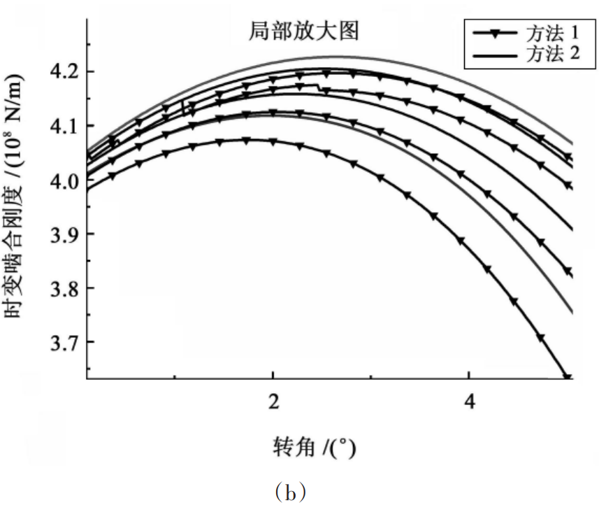
Fig. 5 Comparison curve of time-varying meshing stiffness calculation results
4 Conclusion
1) For spur gears with teeth greater than 41, combined with the cutting geometry and the principle of tooth profile envelope, the difference between the starting point of the involute tooth profile and the intersection point of the involute tooth profile and the base circle is clarified, the tooth root transition parameter curve and a more realistic effective tooth thickness reduction limit line are introduced, the calculation formula of the time-varying meshing stiffness of the traditional potential energy Falun teeth is improved, and a more stringent and more comprehensive calculation model of the time-varying meshing stiffness of faulty gear teeth with different crack degrees is established.
2) Based on the improved crack gear tooth model, the time-varying meshing stiffness of different crack levels is calculated. The calculation results show that the gear with the large tooth count does not correct the gear tooth model when the meshing stiffness changes during the solution
This results in a small calculation result. Root cracks will result in a decrease in meshing stiffness, and a greater reduction in the second meshing cycle. The degree of cracking increases, and the reduction of meshing stiffness also increases.
3) When the crack size is small, the specific form of the effective tooth thickness reduction limit line has little influence on the calculation of time-varying meshing stiffness, and it is recommended to use the straight line as the effective tooth thickness reduction limit line; When the crack size is large
, the straight cut limit line does not correspond to the actual situation of the crack. Compared with the parabola, the oblique line can meet the needs of calculation accuracy to a certain extent, and the modeling is simple, the calculation is convenient, and it has stronger practicability, and it is recommended to use the oblique line as the effective tooth thickness reduction limit line.