
0 Introduction
Compared with traditional involute gears, point-and-line meshing gear transmission has the characteristics of high bending strength, high contact strength, long life, low noise and good separability. In the field of point-line meshing gear transmission, Luo Qihan et al. made a closed diagram of the parameters of point-line meshing gear; Huang Hai et al. proposed a point-line meshing gear contact static strength meter based on the calculation method of contact static strength of involute cylindrical gears Calculation method; Yang Fan et al. In view of the particularity of the tooth profile of the point-line meshing gear, the tooth profile of the point-line meshing gear was fitted and modeled by SolidWorks. Qian Zuoqin et al. carried out experiments on the bearing capacity and noise of point-line meshing gears, and verified that the point-line meshing gears improved the bearing capacity and significantly reduced the noise compared with involute gears. Huang Hai et al. used the multiplier method to establish a mathematical model to optimize and calculate the safety factor of the actual bending fatigue strength of point-line meshing gears. Huang Hai et al. judged the cold gluing of point-line meshing gears, and derived the calculation formula of the minimum oil film thickness. Jin Xiaofeng Through the coordinate conversion and gear tooth profile theory method, the tooth surface equation of point-line meshing gear is obtained. Xiong Wenheng et al. calculated the meshing stiffness of the spur tooth single-point line meshing gear according to the potential energy method, and summarized the corresponding calculation formula. The comprehensive stiffness CR affects the vibration and noise of the point-line meshing gear transmission, and the smaller the comprehensive stiffness, the gear is more flexible, with high impact resistance and low noise. In addition, the combined stiffness also plays a role in calculating the gluing fatigue of gears. The existing calculation of the comprehensive stiffness of point-line meshing gear transmission adopts the calculation method based on involute gear transmission proposed in the literature, which is simple and fast, but the accuracy of the results is low. Based on the potential energy method, a formula for calculating the time-varying meshing stiffness of a straight tooth point-line meshing gear transmission is proposed, but only the accuracy of the method for the meshing stiffness of a single pair of teeth is calculated and verified. On this basis, a formula for calculating the total meshing stiffness including the time-varying meshing stiffness of the double pair of teeth is proposed, and the comprehensive stiffness calculation formula for the spur tooth single-point line meshing gear transmission is derived. By means of finite element simulation, the precision degree of the comprehensive stiffness calculation formula based on the time-varying meshing stiffness is verified.
1 Point line meshing gear transmission meshing features
The point-line meshing gear transmission has both the nature of line meshing and the nature of point meshing, and the gear alignment, one is the pinion that becomes an involute short tooth, and the upper part of the tooth profile of the other large gear is the involute convex tooth profile, and the lower part is the concave tooth profile of the transition curve. As shown in Figure 1, when the large and small gears start from the B2 point, the top of the big gear and the root part of the pinion tooth are engaged in contact with the convex tooth profile, and this process ends from the B2 point to the node P. In addition, the dual-tooth meshing area is before point C, the single-tooth meshing area is from point C to point D, and the double-tooth meshing region is from point D to the end point of meshing B1. When the gear meshes at point M, the top of the bull gear and pinion teeth fit perfectly, and contact marks are formed over a large area around them; The J point is the intersection point between the involute line of the pinion tooth profile and the transition curve, and when meshing at this point, the involute line of the pinion is in contact with the transition curve of the large gear, which is the contact of the concave and convex tooth profile; From point B2 to point M The contact type is convex profile contact, the M-point to B1 point contact type is concave-convex profile contact, and the J-point is a point in the M to B1 process.
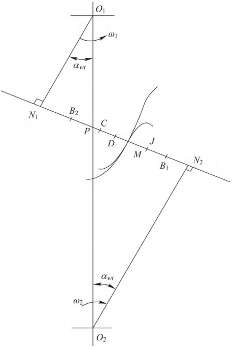
Figure 1 Point-line meshing gear drive meshing position
2 point-and-line meshing of the combined stiffness of the gear drive
2.1 Definition of comprehensive stiffness
According to Ref. [10], the total tooth stiffness Cs is the total tooth normal force per millimeter of tooth width and deformation per micron. The composite stiffness cr is the average of the total tooth stiffness that varies with time during the meshing process, which corresponds to the meshing stiffness cr in the involute gear calculation.
2.2 Comprehensive stiffness calculation based on involute gear transmission
Due to the late start of the research on point-line meshing gear transmission, this method is the result of applying the traditional comprehensive stiffness calculation of involute gears in the early stage, simplifying the complex steps, and approximating the calculation of the comprehensive stiffness of point-line meshing gear transmission to the meshing stiffness calculation of traditional solid involute gears, and most of the formulas used are the empirical formulas in GB/T 3480-1997 “Methods for Calculating the Bearing Capacity of Involute Cylindrical Gears”. Then the formula for calculating the comprehensive stiffness of a solid straight tooth single-point line meshing gear is
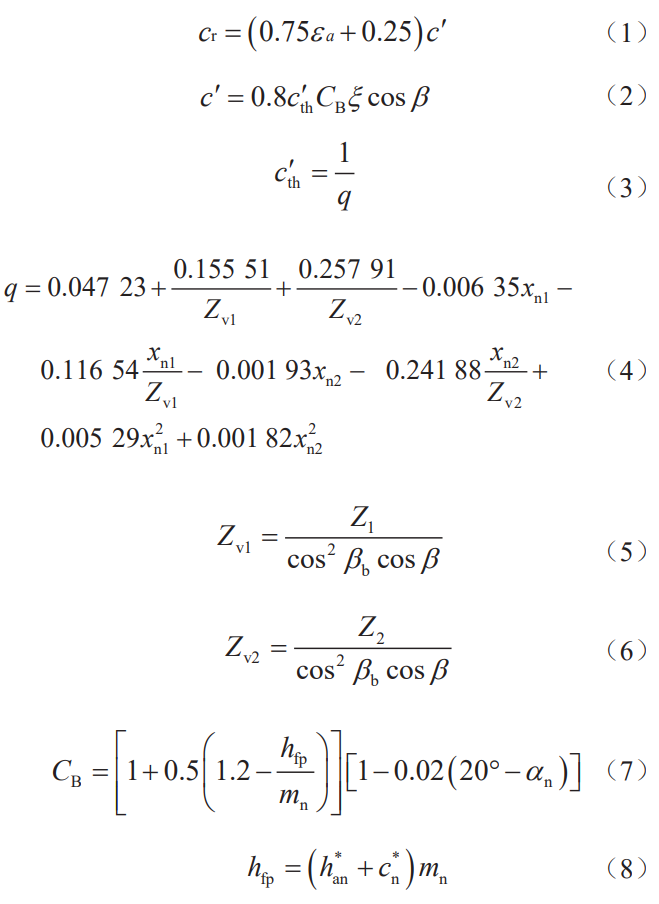
where: εa is the degree of coincidence of the end face; c′ is the stiffness of a single pair of teeth; q is the tooth compliance; CB is the basic tooth profile coefficient; αn is the pressure angle of the indexing circle of the normal surface of the basic rack; ξ is the coefficient, and the material of one gear is steel and the other gear material When the same is steel, ξ=1, one gear material is steel, and the other gear material is cast iron ξ=0.74, when one gear material is cast iron and the other gear material is cast iron
ξ=0.59。
2.3 Calculation of time-varying meshing stiffness based on potential energy method
According to the relevant research in the references, when calculating the time-varying meshing stiffness of the straight-tooth single-point line meshing gear transmission, the calculation of the time-varying meshing stiffness is based on the meshing of 1 pair of teeth and 2 pairs of teeth in the meshing process, and the segmentation is divided into the calculation of the meshing stiffness of single tooth pair and the meshing of double tooth meshing Stiffness calculations. The formula for calculating the stiffness of a single tooth pair is
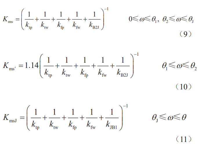
where: Kms is the meshing stiffness of a single pair of teeth before passing through the J point in the double-tooth meshing region (the contact type in this process is the convex tooth profile contact), Kms′ is the meshing stiffness of the straight tooth single-point line meshing gear when the single pair of teeth is meshed (the process is also the contact of the convex tooth profile), and KmsJ is the meshing stiffness of the single pair of teeth in the meshing section of the double-tooth meshing section through J to B1 in the meshing process (since the J point is the intersection of the involute and the transition curve of the large gear tooth profile, the involute line of the pinion and the large gear tooth profile). Transition curve contact, which is the concave-convex tooth profile contact contact), ω is the tooth The angle between the center line of the wheel and the meshing point, θ1 is when the gear is meshed in the double tooth pair , θ2 is the angle at which the gear is meshed in a single tooth pair, and θJ is when the large gear The demarcation point of the transition curve, point J, engages with the involute on the tooth profile The angle of rotation of the wheel, θ is the angle at which the gear completes the complete meshing transmission cycle, ktp is the single-tooth stiffness of the driving wheel, kfp is the stiffness of the base of the driving gear tooth, and ktw is The stiffness of the single tooth of the driven wheel, kfw is the stiffness of the base body of the driven tooth, and kB2J is the gradual The contact stiffness of the open tooth profile, kJB1 is the contact stiffness of the concave-convex tooth profile. The formula for calculating the meshing stiffness of the double tooth pair is
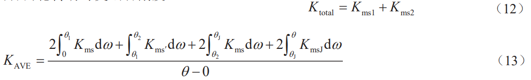
where Kms1 is the meshing stiffness of the first pair of teeth and Kms2 is the meshing stiffness of the second pair of teeth.
2.4 Comprehensive stiffness study based on time-varying meshing stiffness
According to the definition of comprehensive stiffness, it can be seen that the comprehensive stiffness of point-line meshing gear transmission is essentially the average value of the meshing stiffness that varies with time in the meshing process in a certain period of time. Therefore, the meshing stiffness at a certain moment calculated by the potential energy method cannot be directly calculated with the composite stiffness The results are compared and studied, otherwise a large error will be generated. In this regard, the solution proposed in this paper is to average the time-varying meshing stiffness obtained by the potential energy method in the form of calculus, which is consistent with the comprehensive stiffness property in the reference. In order to compare with the comprehensive stiffness obtained by the formula for calculating the comprehensive stiffness, the results obtained from the 3-segment calculation are averaged, where: KAVE is the meshing stiffness of the point-line meshing gear mesh The average value of 0 ~ θ.
3 Simulation verification
In order to further demonstrate the difference between the two methods in calculating the meshing stiffness of gears, the examples analyzed in Ref. [9] were selected: the pinion gear is 28, the tip circle radius is 40.800 mm, the indexing circle radius is 38.500 mm, the pitch circle radius is 37.180 mm, the base circle radius is 36.178 mm, the root circle radius is 35.156 mm, the torque is 477.50 N·m, and the displacement coefficient is +0.039, and the number of teeth of the large gear is 51, and the tip circle radius is 51 68.400 mm, the radius of the indexing circle is 70.125 mm, the radius of the pitch circle is 67.720 mm, the radius of the base circle is 65.896 mm, the radius of the root circle is 62.772 mm, the torque is 4 775.00 N·m, the displacement coefficient is -1.424, the center distance of the two gears is 104.9 mm, the modulus is 2.750 mm, and the tooth width is 30.000
mm, the degree of coincidence of the end face is 1.603, and the normal force is 13 198.57 N. The total meshing stiffness calculated from Eq. (9)~Eq. (12) based on the comprehensive stiffness calculation formula of time-varying meshing stiffness is shown in Table 1. It can be seen that because the segmentation curve is in the range of 0° ~ 7.88°, that is, the gear is meshed in the double teeth
section, 7.88° ~ 12.85° interval that is, the gear is in the single-tooth meshing section,
The interval of 12.85°~20.74° contains the double-tooth meshing section with concave and convex tooth profile contact, and the meshing stiffness in these three sections does not change much, so only some representative parameters are taken for display. The combined stiffness obtained from Eq. (13) is 17.353 4 N/(mm·μm)。 The result of this instance is calculated by Eq. (1) ~ Eq. (8) as shown in the table
2 shown.
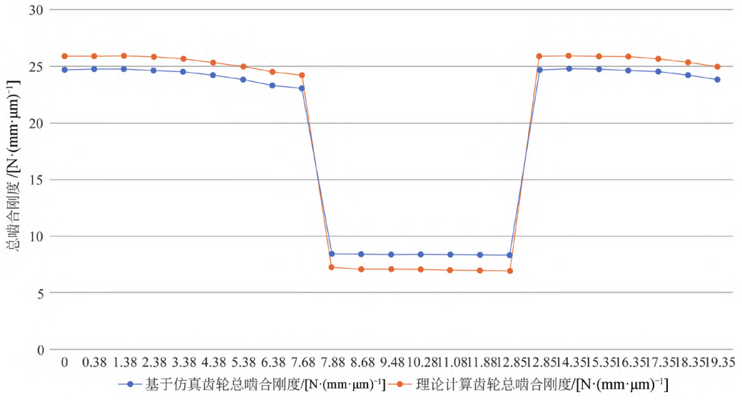
Fig. 2 Comparison of the total meshing stiffness calculated by the potential energy method formula and the simulated total meshing stiffness
Table 1 Total meshing stiffness calculated based on the comprehensive stiffness calculation formula for time-varying meshing stiffness
| 主动轮转角 ω ( / °) | 总啮合刚度 cr [/ N·(mm·μm)-1] |
| 0.00 | 25.87 |
| 7.88 | 7.25 |
| 12.85 | 6.94 |
| 20.74 | 24.23 |
Table 2 The comprehensive stiffness calculated based on the formula for calculating the comprehensive stiffness of the involute gear drive
| 项目 | 结果 |
| hfp | 3.438 /mm |
| Cb | 0.975 |
| Zv1 | 28.00 |
| Zv2 | 51.00 |
| q | 0.071 |
| c’th | 14.164 |
| c’ | 11.048 /[N·(mm·μm)-1] |
| cr | 11.048 /[N·(mm·μm)-1] |
The combined stiffness is 16.044 N/(mm·μm). In order to compare the calculation formula based on time-varying meshing stiffness and the calculation based on involute gear transmission, the calculation is studied The accuracy of the results obtained needs to be verified by finite element simulation.
The comprehensive stiffness is calculated by defining the stiffness, i.e. the load by the deformation. The 3D model was established, and the tooth deformation contour diagram of the large and small gears in the meshing process was obtained by finite element simulation, and the specific gear tooth shape variables were obtained by analyzing the contour diagram. The inter-tooth load values are modeled using the same 3D The finite element simulation is used to obtain the specific load values of each point in the transmission process, and finally the total meshing stiffness is solved. According to the references, the meshing stiffness obtained according to the stiffness definition formula and simulation analysis is the meshing stiffness of a single pair of teeth, and the gear cannot be directly obtained
The total meshing stiffness during the meshing of the double tooth pair must be calculated in the calculation of the double tooth pair mesh In the case of stiffness, the meshing stiffness of the single teeth of 2 pairs of teeth meshing at the same time is added according to the load distribution law, and the total meshing stiffness at the same time is obtained by Eq. (12). The results of the total meshing stiffness calculated by the finite element load simulation results and Eq. (12) are shown in Table 3. The results of the total meshing stiffness calculated by the potential energy method formula are compared with the simulated total meshing stiffness, as shown in Table 2.
Table 3 Verification of the total meshing stiffness of the gear based on simulation
| 主动轮转角 ω ( / °) | 总啮合刚度 cr [/ N·(mm·μm)-1] |
| 0.00 | 24.7 |
| 7.88 | 8.46 |
| 12.85 | 8.33 |
| 20.74 | 23.1 |
The comprehensive stiffness obtained from Eq. (13) is 17.287 66 N/(mm·μm).
The simulation verifies that the composite stiffness is 17.288 N/(mm·μm) based on time-varying meshes
The combined stiffness of the composite stiffness is 17.353 N/(mm·μm) and is based on an involute
The combined stiffness of the gear drive is 16.044 N/(mm·μm). Calculated by knots
As a result:
1) For the spur single-point line meshing gear transmission, the comprehensive stiffness calculated based on the time-varying meshing stiffness calculation formula is about 8.16% compared to the comprehensive stiffness calculated based on the calculation formula of involute gear transmission.
2) For the spur tooth single-point line meshing gear transmission, the calculation result based on the time-varying meshing stiffness calculation formula is similar to the simulation result, with an error of 1.192%, while the error between the calculation result and the simulation result is 7.19%.
4 Conclusion
1) The error between the calculation results of the comprehensive stiffness based on the time-varying meshing stiffness and the simulation results is less than 6%, which shows that the comprehensive stiffness calculation based on the time-varying meshing stiffness has a certain degree of credibility.
2) The comprehensive stiffness calculation based on the time-varying meshing stiffness is characterized by dividing the calculation process by the angle of the active rotation, and the double-tooth meshing zone and single-tooth meshing zone are calculated in sections, which are close to the actual gear meshing process, and the calculation steps are more complex, but the accuracy is higher.
3) The comprehensive stiffness calculation formula based on involute gears is simple, convenient and fast, and can obtain reference results at a fast speed, but because this method refers to the meshing stiffness calculation method of traditional solid involute gears, the calculated data accuracy is low.