
0 Preface
Compared with the ordinary tooth profile, the double circular arc tooth profile increases the meshing of the gearLogarithm reduces the occurrence of sharp points and interference during the meshing of ordinary gears.and significantly improves the gear meshing efficiency.At the same time, its loadHigh capacity, long service life, can work in high speed and high load environmentJobs.Double circular arc gear is an important component of the oil pumping unit reducer, whichInevitably, breakage will occur after a period of use, resulting in direct scrapping and replacementNew gears require higher costsThe main forms of gear damage areThere are broken teeth, tooth surface peeling, etc. To address these issues, current restoration methodsThe case is to repair the double-arc gear with less damage and repair value.Laser cladding or surfacing on the gear, due to the repair of the gear teethIf the outline is not standard, it must be cut to make it a double circular arc for remanufacturing.The gear restores its original performance and accuracy.
At present, many scholars have conducted research on different processing methods for double circular arc gears, and verified the feasibility of CNC machining for double circular arc gears.explored the numerical control machining process of circular arc gears;The overcutting experiment was conducted on a hobbing machine to process double-arc gears, resulting in newan effective method for machining double circular arc gears;established doubleThe equation of the spatial meshing line of the circular arc hob-gear is described,The essence of roll-cutting instantaneous forming is to solve various problems in the design of the hob.Theoretical issues.The above research can achieve the goal of remanufacturing double-arc gear machining,However, the processing efficiency is too low, so it is necessary to design a system that can process singleA machine tool that cuts multiple teeth with damaged teeth or gaps.
1. Single tooth generation theory
Double circular arc gear has irreversible helical surface, so it can only be usedIndexing cutting.The remanufactured double-arc gear is cut using the indexing generating methodIn the process of single tooth machining, only single tooth or interval distribution is required.of the tooth is cut, and the feed sequence is specified as first feeding along the tooth directionThen feed along the tooth profile.According to the principle of kinematics, the necessary and sufficient condition for conjugate two tooth surfaces isThere is a common tangent plane at the contact pointFrom the perspective of physical concepts, if the contact pointThere is no common normal line and there is no contact point between the tooth surfaces of the two meshing gears.For the moving speed vector, the two tooth surfaces will be engaged or disengaged with each other,causing interference phenomena and reducing the continuity of gear transmission.
The mathematical expression of the principle of kinematics is

The stationary coordinate system is defined as K as shown in Figure 1, and the coordinate system Kd andRack tool fixing, coordinate system K1 and the machined double arc gearFixed.
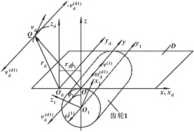
Figure 1 Instantaneous rotation method for single tooth indexing generation
The double-arc rack equation [12-15] is shown in equation (2)
The normal line of the contact point of the remanufactured double circular arc tooth surface is obtained from the above equationvector n is
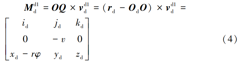
Due to the particularity of the feeding sequence, the single tooth indexing generating process requiresConsider the feed rate along the tooth direction.Use the instantaneous rotation method to solve the instantaneous contactThe relative velocity at point , vyd1d is not at the location of the instantaneous contact point Q, noTo directly add vectors, we need to move them to point Q.To ensure the original effect, add a direction opposite to point QVelocity vector – vd1d , -vd1d and v at point Od1d constitutes the speed couple Md1dAs shown in formula (4):
The velocity vector of the contact point on the remanufactured double-arc tooth surface is obtainedv( d1)d for
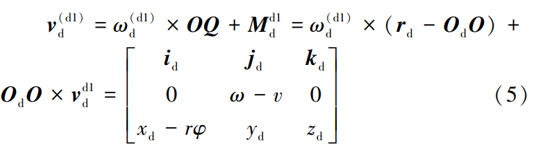
Expand it
Therefore, it can be seen that the single tooth generating process of double circular arc gears meets the conjugate connection requirement.The method of generating single tooth indexing is feasible.
2. Parameters of double circular arc gear and cutting tool
2.1 Parameters of double circular arc gear
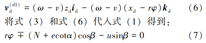
Due to the non-standard gear tooth profile after remanufacturing, its cutting processThis special machine tool is used for cutting the remanufactured double-head screw shown in Figure 2.Single tooth damage or several teeth with intervals damaged of circular arc gear.Double circular arcThe basic parameters of gears are shown in Table 1.
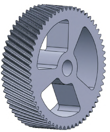
Figure 2 Re-manufactured double circular arc gear
2.2 Parameter design and simulation of double-arc disc hob
The tooth profile of double circular arc gear is relatively complex, which is formed by several segments of circular arcs throughThe complete tooth profile shape formed by connecting certain mathematical relationships。The normal modulus of the double-arc gear to be processed in the article is 4.5 mm,Double circular arc disc calculated and designed according to national standard GB/T 14348-2007The profile of the form hob is shown in Figure 3.Through MATLAB software programming, using the designed double arcSimulate the cutting of double circular arc gears using a disc-shaped hob.First simulate the shape of the hobAfter translating along the spiral direction and then generating, the remanufactured doubleThe single tooth of the circular arc gear is shown in Figure 4, which verifies the feasibility of using the hob shape to cut and remanufacture the double circular arc gear.
Figure 3 Double circular arc disc hob shape

Figure 4 Simulation of cutting a single tooth with a double-arc disc hob
According to the national standard GB/T 14348-2007, the modulus is 4.5The outer diameter of the double-arc hob is 112mm, and the double-arc disc shapeThe hob model is shown in Figure 5.
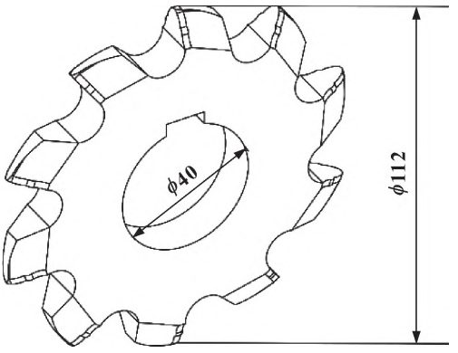
Figure 5 Double circular arc disc hob
3 Design of remanufacturing double circular arc gear single tooth cutting machine
3.1 Analysis of the transmission principle of the machine tool
The remanufacturing method of double circular arc gear has 4 cutting motions:The rotary motion, axial helical feed motion, and tooth profile of the double-arc disc hobThe shape direction is developed into a feed motion and a rotating motion of the remanufactured double circular arc gear.Therefore, the transmission principle of cutting machine tools mainly consists of four transmission chains,As shown in Figure 6.
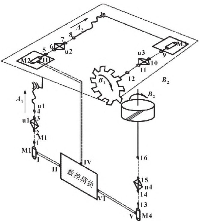
Figure 6 Transmission principle of remanufacturing double circular arc gear machining
(1) Rotary drive chain of double-arc disc hob: motor M3-9-10-u3-11-12-Double circular arc disc hob.Driven by motor M3The double-arc disc hob is driven to rotate by the replacement device sep3.The transmission ratio of the replacement device u3 can achieve variable speed of the tool speed.(2) Axial helical feed drive chain: servo motor M1-1-2-u1-3-4-lead screw.Driven by a stepper motor and driven by a replacement deviceThe screw rod and the double-arc disc hob rotating transmission chain cooperate to complete the axial spiralThe feed speed of this transmission chain refers to the processing and remanufacturing of dual circlesTangential cutting speed of the tool for the arc gear.Changing the transmission of the replacement device uonThe speed ratio can be adjusted to achieve variable speed of screw feed.(3) Forming a feed drive chain in the direction of the tooth profile: servo motor M2-5-6-u2-7-8-lead screw.Driven by stepper motor M2, it is replaced byThe device uu2 drives the screw to rotate, and then drives the tool to rotate the transmission chainLinear motion.The direction of the tooth shape is developed into a motion law similar to that of a gear and rack transmission.Therefore, the feed speed of the transmission chain is determined by the rotational speed of the workpiece.ChangingThe transmission ratio of the replacement device u2 can achieve variable speed of generating feed.(4) Rotary transmission chain for remanufacturing double-arc gears: servo electricMachine M4-13-14-u4-15-16-workpiece.Driven by stepper motor M4The rotation of the gear is driven by the replacement device 4.The formation of the helical angle causesThe determination of the rotational speed of the workpiece in this transmission chain depends on the helical feed in the tooth directionThe feed speed of the transmission chain.Changing the transmission device of the transmission chain u4The ratio of motion can achieve variable speed of the workpiece rotation.The remanufacturing double-arc gear single-tooth cutting machine tool also designs three digitalControl transmission chain.It is used to realize the numerical control connection between stepper motors, which not onlyEnsure that the feed of the hob along the spiral line and the helical angle meet the design requirements, andEnsuring the tool and gear form a generating motion relationship.
3.2 Design of Machine Tool Structure
The remanufacturing double-arc gear single-tooth cutting machine tool is shown in Figure 7,The machine tool consists of a tool moving part, a tooth helical feed part, a tooth profileIt consists of a feed unit, a workpiece moving unit, a tool setting unit, and a frame.
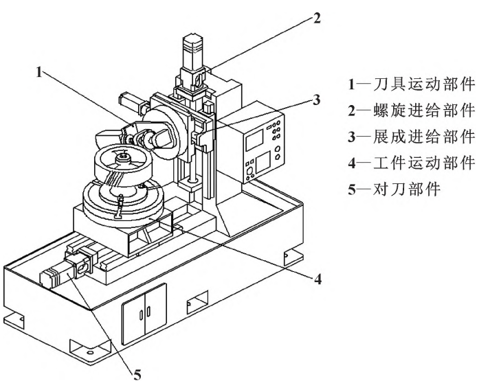
Figure 7 Remanufactured double-arc gear single-tooth cutting machine
The moving parts of the workpiece are shown in Figure 8, which can realize servo electricalThe machine drives the workpiece to rotate.The workpiece loading base is driven by the workpiece movement servo motorDriving, which can realize the processing of different sizes of gears and precise controlDistance between the disc hob and the gear.The rotation of the gear is controlled by the workpiece rotation servoThe machine is driven by a worm gear and worm, which transfers power to the gear fixture to ensureConsidering the influence of axial pitch deviation on the machining of gear rotation accuracy mold coreset up a reducer at the servo motor that drives the workpiece to rotate to reduceAxial pitch deviation.
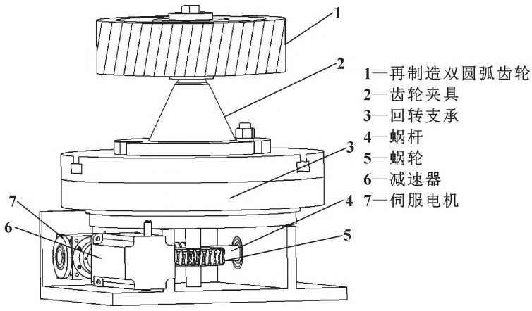
Figure 8 Moving parts of workpiece
4. Analysis of machine tool processing errors
The machining error of remanufacturing double circular arc gears refers to the cutting error of a single toothAfter machining, the appearance of the gear is similar to the theoretical design of the double-arc gear.The size deviation between them directly affects the remanufacturing of double circular arc gearsThe following mainly discusses the machining quality of gears during the process of machining along the helical line.The error caused by directional feed.Search for the national standard GB/T 15753-1995 “Arc Cylindrical ToothWheel accuracy can be affected by the production process along the spiral direction.The machining error of the circular arc gear has the greatest impact on the axial pitch deviation, as shown in Figure 9as shown.Considering the total torque and safety factor required for driving the wormAfter selecting the motor and its rotor torque, the motor is selected as shown in Table 2.
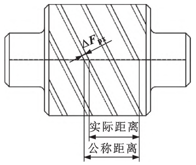
Figure 9 Axial pitch deviation of circular arc gear
At this time, the angle θ1 of the gear rotation is 0.02069°, and the helix angle of the hob isThe feed rate is 2.55441 m/min.Each rotation of a step angle, the rollerThe displacement of the knife along the axis s2 is 0.1999×10⁻⁴m.-3m, defined by the helical angle
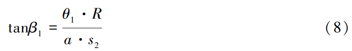
Wherein: θ1 is the rotation angle of the workpiece, (°);R is the half length of the workpieceR, m;a is the number of step angles;s2 is the tool displacement, m;β1 isTheoretical helical angle, (°).Substitute the parameters into a = 14.3967, and take a2= 14, substitution(8) Actual helical angle β2= 24.0011°, resulting in a remanufactured doubleAxial pitch deviation of circular arc gear.The axial pitch deviation of the remanufactured double-arc gear is shown in Figure 10.The dotted and solid lines are theoretical and actual spiral lines, respectively.Within the tooth width range,The axial pitch deviation of gears is not the same, so the axial pitch deviation of gears is calculatedThe limit deviation of tooth pitch F’px is necessary, and the calculation formula is as follows (9):
F′px= ( b·tanβ2- b·tan β1 )·sin ( 2β2- β1 ) ( 9)Where: β1 is the theoretical helical angle, (°);β2 is the actual helical angleα is the angle (°);b is the tooth width, mm.Substitute the parameter to get F′ px= 40. 85μm。
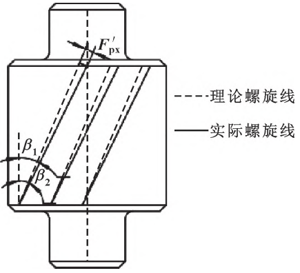
Figure 10 Axial pitch deviation of remanufactured double-arc gear
The tooth width b of the dual circular arc gear to be processed and remanufactured is 80 mm, according toThe accuracy requirements for double circular arc gears used on the reducer of the pumping unit, set the accuracy level of the remanufactured double circular arc gear machining machine tool to level 8, and search for nationalStandard GB/T 15753-1995 “Precision of Circular Arc Cylindrical Gear” can be obtained,The axial pitch limit deviation of circular arc gear, Fpx, is 25 μm, which does not meet the requirement of plusDue to the requirement of working accuracy, a speed reduction mechanism is set up at the motor that drives the workpiece to rotatethan iThe reducer with a reduction ratio of 7.2 is used to reduce the axial pitch deviation.At this time, the motor that drives the workpiece to rotate rotates by one step angle, and the workpieceThe rotation angle θ′1 is 0.00287°, which is substituted into formula (8) to obtain a2=1.9995, take a’2= 2 Substituting (8) into the actual helical angle β′2=23.388°, theoretical helical angle β1= 23.4117°, helix angle errorFurther reduce it and substitute it into equation (9) to obtain F’px= 15. 51μm<Fpx=25μm meets the accuracy requirements.
5 Conclusion
According to a new feeding sequence of first tooth direction and then tooth shape,Overall scheme of remanufacturing double-arc gear single-tooth cutting machine tool.Conclusion:(1) Verified the re-integration method based on the principles of kinematics and instantaneous rotation method.Feasibility of single tooth machining for manufacturing double arc gears, which will be used for subsequent machine tool designProvide theoretical basis.(2) Based on the existing structure of the double-arc hob, aSpecial tool for single tooth machining of remanufactured double arc gears.The principle of motion is applied to the moving parts of the tool, the helical feed components of the tooth profile, and the development of the tooth profile.Four important components, including the feed components and the workpiece moving components, have been designedFinally, the remanufactured double-arc gear single tooth that meets the processing requirements is obtained.Cutting machine tool.(3) Analyze the single tooth machining error of remanufactured double arc gears,The method of reducing the axial pitch error of remanufactured double-arc gears was studied.