
0 Introduction
Large bevel gears are widely used in important fields such as power generation, ships, and mines.In recent years, with the development of large-scale lifting machinery, metallurgical industry, mining machinery,With the continuous development of heavy machinery industries such as machinery, more and more manufacturers have an increasing demand for large straight bevel gears.Large straight bevel gearsIt has the characteristics of large structural size and difficulty in manufacturing teeth. Its manufacturing capability is a concentrated reflection of the core competitiveness of advanced manufacturing.This structure has become a common structure for existing oversized straight bevel gears.
1. Analysis of side milling of tooth surface
When the end mill is cutting along the tooth surface of the spur bevel gear, the position of the tool is determined by a series ofThe coordinates of the cutter center M of the column and its corresponding cutter axis vector P are determined, and the same cutter axis vector P and the correspondingThe normal vectors N of the corresponding tooth surfaces are in a vertical relationship.The tool center coordinates determine the cutting tool’sThe orientation and attitude of the tool at the center coordinate are determined by the tool axis vector.End millThe schematic diagram of side milling is shown in Figure 1.When machining gears using traditional methods, the rotation center of the gear often does not coincide with the rotation center of the machine tool.The center of the workbench coincides, and as the workbench rotates regularly, the tool used to process each tooth grooveThe position is repeated continuously, enabling the processing of all gear teeth and slots.Split wheel blank and machine toolThe positional relationship diagram of the workbench is shown in Figure 2. At this time, the center of the split gear blank is a certain distance from the center of the machine tool’s rotary table.so that the position and posture of the tool for processing each tooth slot are different.Figure 2 Position relationship diagram of the split wheel blank and the machine tool tableAccording to the tooth profile characteristics of straight bevel gears, rough machining is performed usingForming method processing, using forming tools such as finger-type milling cutters.This article focuses onThe research of end milling for side milling is aimed at the finishing of tooth surfaces.When the processing starts, the tool surface is tangent to the theoretical tooth surface, fromStarting from the top of the gear, the end milling cutter starts from the large end and follows the gearCut the conical generatrix and move it to the small end of the gear.Then,Cut from the small end to the large end, with the tool moving back and forth in a zigzag patternThe shape of the cutting path until the entire tooth surface is processed and refined.The tool path planning is shown in Figure 3.Using this pathThe calculation of the tool location point during processing is relatively easy, and the tool can be easily aligned along theWith the movement of the tooth surface busbar, the processing accuracy and post-processing of the tooth surfaceThe knife pattern is easier to control.The spacing between the knives is determined according to the machining accuracy and tooth surface finish requirements.At the same time, the zigzagThe tool path also reduces the time of the tool’s idle stroke, thereby improving the production and processing efficiency.For the tooth surface processing of the integral straight bevel gear, it canAutomatic machining programming in UG software, but the generated machining path is different from the manually programmed path.For split straight bevel gears, their geometric centers fall outside the machine tool. If automatic machining programming is to be performed in UG software, the difficulty will be greatly increased.
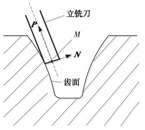
Figure 1 Schematic diagram of side milling with end mill
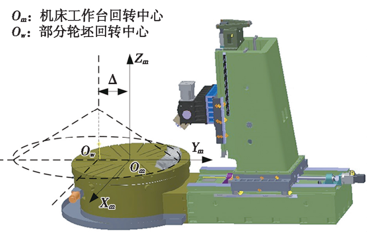
Figure 2 Position relationship diagram of the split wheel blank and the machine tool table
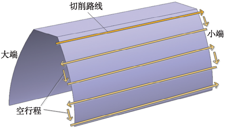
Figure 3 Cutting path planning for finishing
2 Solution of side milling tool location
According to the forming characteristics of the side milling process, a model is established as shown in Figure 4The indicated split machining coordinate system:SO(OO~Xo, Yo, Zo) is the coordinate system connected to the wheel blank,The origin is located at the apex O of the base cone of the split wheel blank, with the Z axis passing through the baseThe center of the cone base.By calculating allThe coordinates of the tool center and the tool axis vector are obtained to obtain the tool orientation in the split machining process.Spatial position and posture.Sc (Oc ~ ic, jc, kc) is the coordinate system fixed to the tool, and the originThe point is the center coordinate of the tool, and the direction of the instantaneous tool axis vector is used to express the motion of a series of tool feature points and the deflection angle of the tool.Figure 4 Coordinate system for split machiningAccording to the tooth surface equation of a straight bevel gear, the theoretical tooth profile of a straight bevel gear can be obtained by solving the equation.The surface is regarded as a curved surface swept by a curve according to a certain motion law,In terms of its geometric significance, this surface is called a ruled surface, which is composed of straight linesThe surface formed by the continuous motion trajectory is shown in Figure 5.
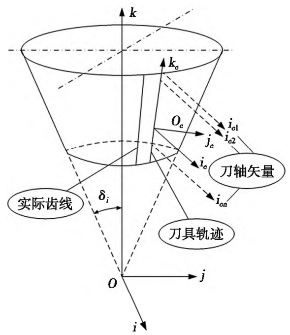
Figure 4 Coordinate system for split machining
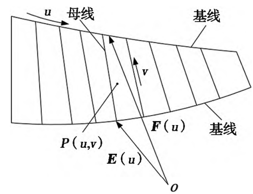
Figure 5 Formation of straight grain surface
Figure 6 is a schematic diagram of the formation of the tooth surface of a straight bevel gear, where the position of the tool center coordinate is determined byThe size of the normal vector on the tooth surface and the radius of the end mill jointly determine the coordinates of the tool center. To solve the coordinates of the tool center, it is necessary to first calculate the normal vector corresponding to each point on the tooth surface.The vector.
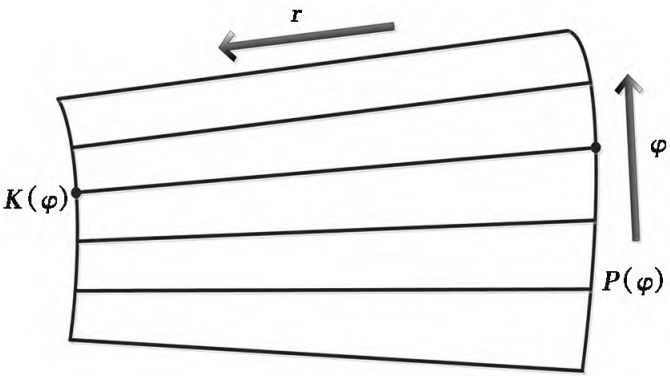
Figure 6 Schematic diagram of tooth surface formation of straight bevel gear
3 Processing simulation
In order to improve processing efficiency, the rough slotting of the split spur bevel gear is first completed by a three-axis CNC machine tool. The rough machining uses a forming method toThe use of finger-type milling cutters for slot milling is not the focus of this article due to their low accuracy requirements and simple processing.In the VERICUT software,The machine tool model that meets the requirements of tool position solving and post-processing is shown in Figure 7.Set the tool parameters, load the calculation, and obtain the NC processing parameters.The simulation process of the finishing process is shown in Figure 8.
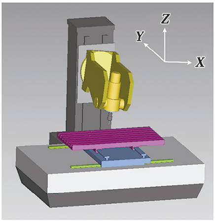
Figure 7 Machine Tool Model
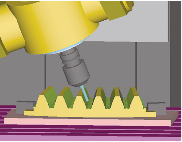
Figure 8 Finishing simulation process
After completing all simulation processes, use the VERICUT softwareThe automatic comparison function of theThe design model of the bevel gear is imported into the VERICUT software,Reasonably set the over-cut and under-cut comparison tolerance to 0.05 mm, and automatically compareThe results are shown in Figure 9.From Figure 9, it can be seen that in the process of end milling,On the tooth surface of the gear, there is undercutting in the form of points, and there isThere is a small amount of residual material locally, and there is a small amount of local overheating at the large end taper of the gear.The rest is consistent with the theoretical tooth surface.The underside of the tooth groove isThe reason is that the bottom surface of the tooth slot has not been finished.Simulation resultsIt shows that the method of using end milling cutter to machine split straight bevel gears is correct and feasible.
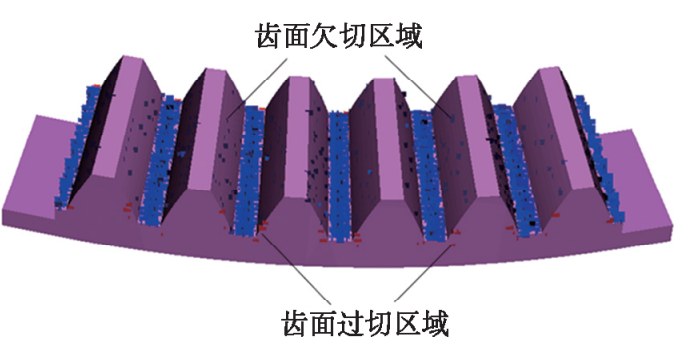
Figure 9 Automated comparative analysis results of VERICUT software
4 Processing and measurement experiments
To further verify the correctness of the calculation results, the tooth surface cutting of straight bevel gears was carried out on the DMU100 five-axis CNC machine toolProcessing experiment.Before finishing, use a finger-type milling cutter for roughing, leaving a finishing allowance of 0.1 mm, and then use a φ10 mm end mill for finishing.The finish machining of the tooth surface of the straight bevel gear is completed.Figure 10 Measurement of the tooth surface of the three-coordinateAfter the tooth surface finishing is completed, use the Hexagon three-coordinate measuring machine to measure theThe tooth surface is measured.Prior to measurement, relevant parameters need to be set.First establish a gear measurement coordinate system in the three-coordinate machine, and perform the datum plane fittingSet the bottom surface of the workpiece placement position as the measurement positioning reference plane, and setThe origin of the coordinate system is consistent with the origin of the section wheel blank.Use the Hexagon self-Use software programming language to develop gear measurement programs, set measurement paths, and communicateRun the gear measurement program to measure and obtain the actual data of the tooth surface, and obtain the measuredThe coordinate values of the measuring points are sorted out through a self-developed program, and the theoreticalThe values were compared with the measured values, and the data were converted into reference values for measuring the gear. The results of the tooth profile deviation are shown in Figure 11.In Figure 11, 1, 3, 5, and 6 represent the order of the measured teeth in the entire gear.From the figure,It can be known that the maximum deviation Ff of the tooth profile of the gear being tested is 5.6 μm, and the maximum deviation ff of the tooth profile shape tolerance is 2.6 μm.
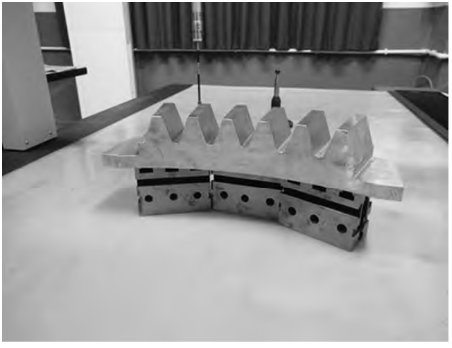
Figure 10 Measurement of the tooth surface of the three-coordinate
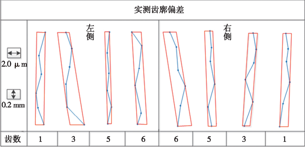
Figure 11 Analysis Results of Tooth Profile Deviation
The result of the pitch limit deviation is shown in Figure 12, and the measured pitch limit deviation value fpt of the gear is 25.3 μm.The cumulative pitch deviation result is shown in Figure 13, and the total cumulative pitch deviation Fp of the measured gear is 21.8 μm.
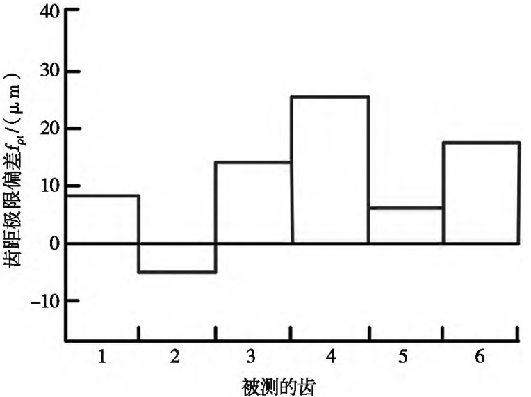
Figure 12 Results of limit deviation of tooth pitch
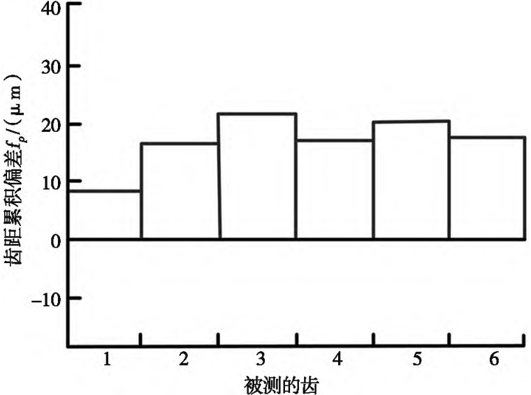
Figure 13: Cumulative pitch deviation results
The radial runout deviation result is shown in Figure 14, and the measured toothThe radial runout deviation Fr of the wheel is 38.3 μm.Based on the measurement results and deviation values of Figures 11-14,According to the analysis, all the processing deviation values are in accordance with the mechanical design manual.The standards stipulated are within the normal range and have been achievedGB/T 10095.1Grade 7 and specified oversize straight teethPrecision standards for bevel gears.
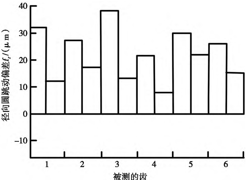
Figure 14 Radial runout deviation results
5 Conclusion
1) The use of end milling methods can provide fine machining of the splitIt is a type of straight tooth bevel gear, which is a super large split straight tooth bevel gearThe manufacturing of wheels provides a new possibility.(2) Based on the calculation of the tool position during the side milling process of end mills,The post-processing mathematical model is correct and the processing path planning is feasible.(3) This research can realize the processing of oversized gears on small machine tools, which can greatly reduce the manufacturing cost of large straight bevel gears, and has the advantages ofand it has a certain engineering application value.