From large-scale equipment in aerospace, shipping, power plants and other fields to daily lifehome appliances, cars, workbenches, and transmission machinery with gears as the main body arean important part of modern industry, in transportation, energy and people’s lifeplay an irreplaceable role.The modern gear transmission system is moving towards high speed,gear grinding heavy load,developing in the direction of high-power, low-noise, and lightweight, but due to the increase in power transmission andThe excitation force increases continuously with the decrease of damping, and the vibration continues to increase, soResearch on the dynamic performance of gear meshing has attracted much attention.Resonance is a common problem in high-speed gearOne of the main causes of failure;secondly, tooth wear is also a cause of gear failureOne of the main reasons for wear is related to temperature, lubrication, load, material,Helical Gear and other factors.Random factors are nonlinearly correlated, with obvious randomness and slow time-varying characteristics.gear grinding Therefore, this article seeks a reliable method to evaluate the wear amount of gear tooth surface.The reliability of the wear amount of the gear tooth surface is analyzed by using the analytical method.
1. Time-varying meshing stiffness analysis of gears
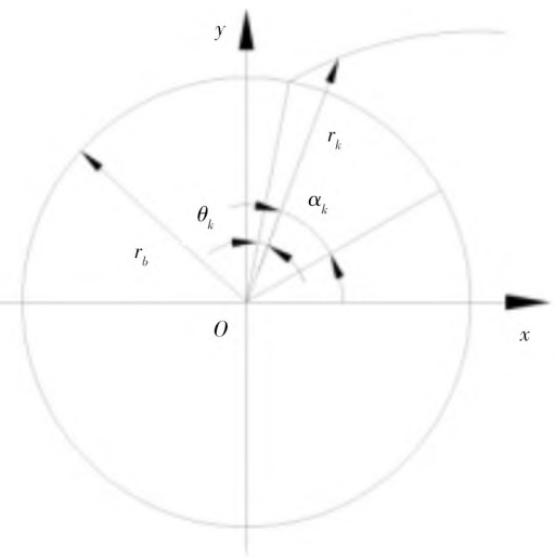
The theoretical model for calculating the dynamic excitation of gears is established, and a parametric finite element model of involute tooth profile meshing is established using ANSYS.Time-varying meshing of gears during meshingAlso known as comprehensive stiffness, the method of calculating elastic deformation uses finite element numerical methodsThe method is represented as shown in Figure 1, Helical Gear which shows the combination of rectangular and trapezoidal gear teeth.According to the shape of the gear tooth in Figure 1,gear grinding the parameters are calculated as follows:
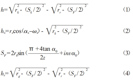
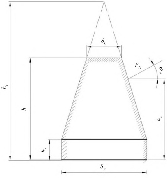
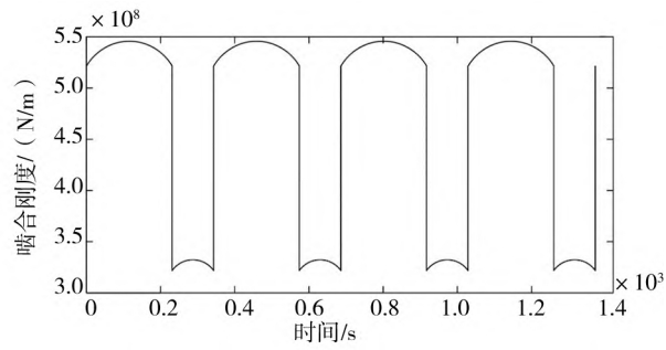
According to formula (4), the deformation of a single tooth, δ, can be calculated by substituting the parameters.Then,gear grinding The meshing stiffness curve of a single tooth is obtained, and finally the gearThe meshing stiffness curve is shown in Figure 2.
2. Establishment of finite element model for virtual prototype of gear meshing
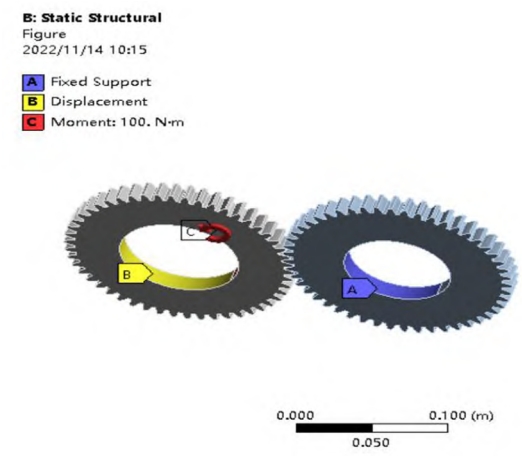
ANSYS provides three types of finite element models for gear meshing virtual prototypingContact schemes include point-point contact, point-surface contact, and surface-surface contactThe contact between gears may seem like a line-to-line contact problem, but in fact, it is a surface-to-surface contact problem.During the actual meshing process, due to the deformation of the forces between the gears, Helical Gear it becomes a surface-to-surface meshing.The surface contact problem, and due to the relative sliding between the meshing surfaces, leads toThe position of the nodes on the contact surface is not fixed during interaction.During the gear transmission process, the external load mainly comes from the work of the driven wheel.as the driving torque of the resistance and the driving gear.Assuming that the teeth of the two gears are in contactAt the moment,gear grinding the driven wheel is fixed and the driving wheel rotates on a fixed axis, resulting in a radial displacementand the constraint of zero axial displacement, apply Ux, Uy,Uz fixed constraint, Helical Gear with the Z axis of the driving wheel as the axis, and applying aAdd Ux and Uz constraints,gear grinding and maintain its rotational degree of freedom Uy. As shown in Figure 4.
3. Analysis of gear torsional vibration reliability and reliability sensitivity
During the gear meshing process, transmission errors occur, which can lead toIt causes strong shock, vibration, gear grinding and noise, and can therefore be considered as a torsional vibration of gears.A form of dynamic failure.Helical Gear Using response surface method to establish the gear meshing transmission errorPoor limit state function, based on which the reliability is calculated using the Monte Carlo method and analyze the influence of each parameter on the reliability of meshing transmission error.
From the crossing rate curve, it can be seen that the crossing rate is 0 at the beginning of the curve, andThe wear amount generated during the machine process did not exceed the threshold, indicating a reliability of 1.As time increases, the crossover rate begins to increase, gear grinding and the reliability begins to decrease.Substituting the rates into the equation, Helical Gear we obtain the wear reliability curves of the driving gear and the driven gear during the working period, as shown in Figure .
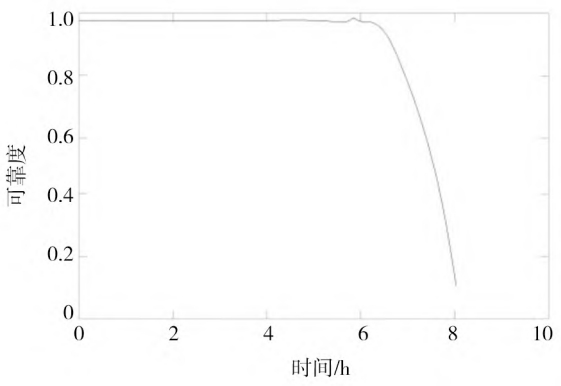
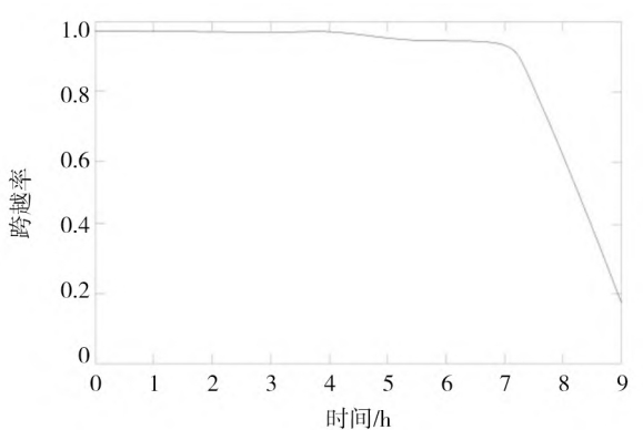
As shown in the figure, the wear reliability curve of the driving gear starts from 6 hoursThe speed began to drop rapidly, reaching its lowest point in 8 hours, and the driven gear was worn reliablyThe degree curve drops sharply at 7 h and reaches its lowest point at 9 h,Helical Gear gear grinding from which it gradually increases.Due to the consideration, the number of meshing times of the driving gear teeth should be greater than that of the driven gear teethIt’s because of the wheel gear.
4 Conclusion
(1) This article uses response surface method and Monte Carlo method to study the stochastic parametersthe reliability and sensitivity of the transmission error of the meshing vibration of several pairs of gears,making the reliability analysis of complex structures simple and efficient.(2) Conduct distribution test simulation of tooth surface wear, combined with reliability theoryResearch on the reliability of gear tooth surface wear and mechanical wear reliabilityResearch is of great significance.(3) Combine the friction coefficient, surface strength, gear grinding and service life of the gear surfacefactor, analyzed the reliability of gear wear, Helical Gear and carried out the research on tooth surfaceResearch provides a theoretical basis.
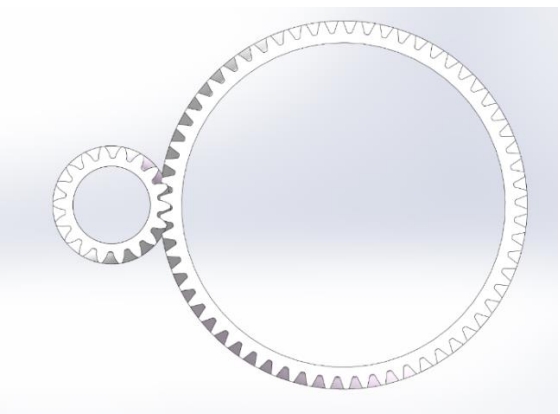
The 3D model of the transmission helical gear was provided by Camnetics for the SOLIDWORKS software
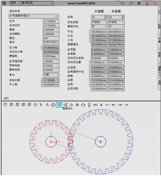
GearTrax is established. GearTrax can quickly create solid molds for spur gears, helical gears, racks, and more in SOLIDWORKS Type. The GearTrax interface is shown in the figure.
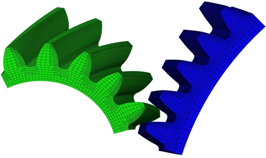
Import the 3D model of helical gears created with the GearTrax plug-in into professional finite element pre-processing software Hypermesh.Helical Gear Since the analysis of the helical gear dynamic meshing process is a typical high nonlinearity In order to ensure the accuracy of the finite element analysis results, the simulation requires a large amount of computation and a high requirement for mesh quality
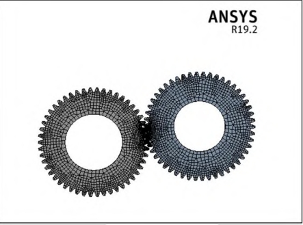
Highly cost-effective and time-efficient, mesh and mesh the individual teeth of the large and small pinions,Helical Gear and mesh the contact area and teeth The mesh at the root is encrypted and then composed into five pairs of meshing teeth, and the final number of finite element model meshes is 147050, the number of nodes is 191109, and the meshed model is shown in Fig.