
Introduction
Modern mechanical equipment has raised the requirements for power density, efficiency and low carbonWith the increasing requirements, gears, as the core of mechanical transmission,One of the components of the heart, its meshing quality and transmission efficiency are affected by humantheir close attention.In order to obtain better meshing performance, the tooth surfaceShaping technology has been widely applied in gear design.This study investigated the effects of different shaping methods and shaping amounts on the transmission performance of gears.The influence of wear can be optimized by modifying the tooth surface based on factors such as minimum wear, and analyzing the relationship between tooth surface wear and system dynamics.The relationship between responses.By modifying the 5 directionsThe shaping coefficient of the gear achieves the free control of the topology structure of the small gear tooth surface.system, and verified the topological modification method by using the example analysis and cutting test.The effectiveness of the method.In order to improve the machining accuracy of gears, a sand profile optimization method for topology-modified gears was studied.A gear with a topology-modified surface for grinding processing is proposedoptimization solution method for machine tool motion parameters.A method for calculating the differential surface of spiral bevel gears using contact point rotation error(ease-off) parameter method, the literature has improved the ease-offanalytical method, and gives the calculation process of solving the machining parameters of spiral bevel gears using the surface synthesis method.At the same time, the topological modification of the gear is also discussed.Design combined with friction power consumption analysis of tooth surface, promoting low power consumption of tooth surfacedesign.Through load contact analysis (loadedtothcontact analysis (LTCA) and mixed lubrication (mixedanalysis of the results of the last hydrodynamic simulation (MEHL)and proposed a multi-objective optimization of the performance of hypoid gear transmissionmodel.The change in tooth surface roughness was calculatedThe friction coefficient was studied to investigate the influence of friction on the meshing stiffness.Regression of mEHL friction coefficient is givenThe calculation formula is used to study the meshing efficiency of hypoid gear pairs.tooth contact area of the gear TCAanalysis model and multi-body friction model, taking into accountThe boundary conditions of MEHL lubrication were analyzed, and the effects of wear on transmission efficiency andNVH (noise, vibration and harshness) dynamicsInfluence.Established EHL conditionsMathematical models for predicting the oil film thickness and friction coefficient of bevel gears are developed.The friction and wear characteristics of helical gear tooth surfaces were studied,The calculation method of adhesive wear on the tooth surface under quasi-static and dynamic loads is given.However, the topology design of the tooth surface is highly coupled with the parameters of the EHL model.The complexity of tooth surface geometry and EHL parameter calculation limits the tooth surfaceThe development of tribology, especially the high-speed reduction of space structures,Bihar hyperboloid (high reduction hypoid, HRH) gearFew people have dabbled in it. However, the HRH gear structure is compact and easy to realizeHigh transmission ratio, widely used in highly integrated electromechanical transmission fieldThe application prospect is extensive, but currently the EHL lubrication of HRRH tooth surfaceThe characteristics and mechanism are still unclear.
1 Gear geometry modeling and analysis
Gear meshing transmission is a typical transmission mode with relativelyGeometric calculation and motion analysis of spatial meshing transmission with large offset distanceComplex, this article is based on the principle of dual conjugate meshing of cutting toolsits geometric analysis and contact parameter calculation method.
1.1 Dual Equal Tangent Conjugate
As shown in Figure 1, the small wheel coordinate system S1 (O1x1y1z1)In the coordinate system of the large wheel processing, the coordinate system of the cutter head is S c(OcxcYale czc) is located in the first quadrant of the shaking table coordinate system Sg ( Ogxg y g z g)The initial position of the quadrant and the rocker coordinate system Sg and the machine coordinate systemS m2 (O m2 x m2 y m2 z m2) overlap, S f (O f x f y f z f) make the small wheelIn the dual meshing position with the large wheel, the two axes intersect at point O f, and the small wheel axis is collinear with xf in the same direction.The initial position x1 is in the same direction aszf.Collinear, y1 and yf are in opposite directions, q2 and Sr2 are the angular and radial tool positionsγm2 is the installation angle of the wheel blank, Xb2 is the bed position, and Xd2 is the axial wheel position.The imaginary production wheel is a blade disc without thickness (Figure 1),While cutting the large wheel, also cut the small wheel by the same amount according to the tooth ratio of the small wheel.The tooth surface, then the small wheel and the large wheel must be conjugate,The rolling ratio of the shape wheel is mg1.During the production process, the small wheel rotates around thex f (z1) axisThe line rotates, with an angle of φ1=mg1φg.
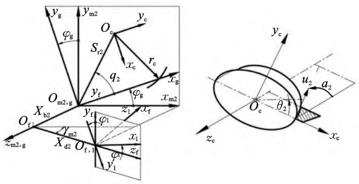
1.2 Tooth surface processing parameters and geometric modeling
Take the 3:60 HRRH gear as an example, the outer diameter of the large wheel145mm, small wheel offset 40mm, large wheel tooth width 20mm.Both the large and small wheels are shaped in two directions to ensure point contact, and the calculation is addedThe operating parameters are shown in Table 1.
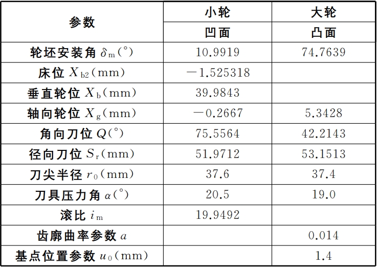
The tapered surface of the tool and the modified tooth surfaces of the large and small wheels are mutually equal cuttingYoke relationship, one-to-one mapping between three planes, based on HRRH gearProcessing parameters, digital solution for tooth surface [8, 15], can obtain smallThe actual tooth surface equation of the wheel is r1 (u1, θ1).Then the relative modification of the large and small wheels isThe amount of
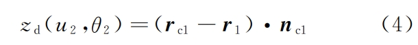
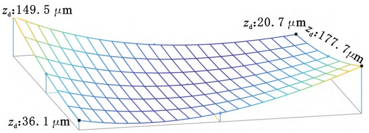
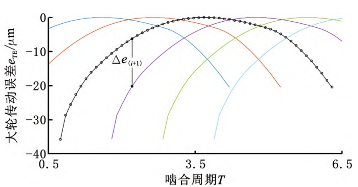
From this, we can draw the ease-off surface shown in Figure 2.Then, we can calculate the ease-off curve by solving the equationThe analysis of the off surface can obtain the tooth surface contact trace points and contact areas shown in Figure 3.The line clearance and the ease-of-off deviation of all trace points constitute the tooth surfaceTransmission error ( TE), as shown in Figure 4The indicated (engagement cycle T is 2π/z2).The six transmission errors in the figureCurve overlap indicates that the degree of coincidence reaches 6 or more, HRRH gearand has high coincidence characteristics.
2 Calculation of geometric motion parameters
2.1 Large gear tooth surface curvature
The large wheel is processed by forming method, and the vector function of the large wheel tooth surface isFor r2(u, θ), the two tangent directions of the curvilinear coordinates are the two principalDirection:
2.2 Differential curvature of contact points
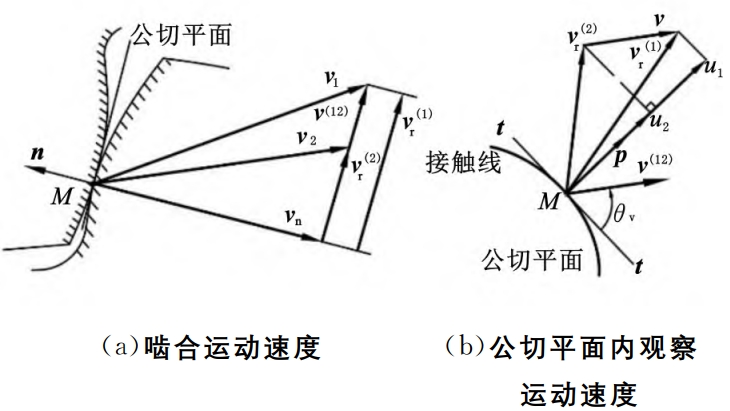
The comprehensive curvature of the contact point is both a geometric parameter andmechanics, lubrication parameters, and the two main values of the comprehensive curvature (t,As shown in Figure 3 and Figure 5, t is the tangential direction of the contact line, and p=The t direction is perpendicular to n. The difference curvature in the t direction is shown in Figure 3.The induced normal curvature in the direction of p can be calculated using the second-order characteristic function Calculation of number ΦII and eigenvector:
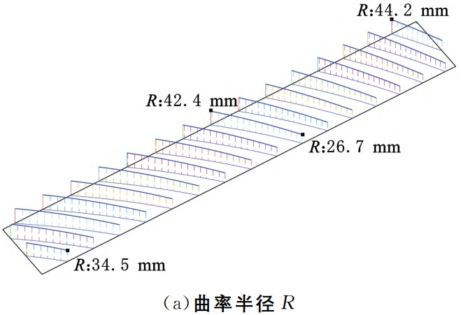
Each point on the contact line is represented by the radius of curvature R=1/KpThe integrated curvature radius value is shown in Figure 6a.Integrated in the direction of pThe curvature radius presents small at the small end and large at the large end, with small tooth root and large tooth tipDistribution trend.Many literatures replace the contact line with contact trace parametersThe parameter calculation is not accurate.
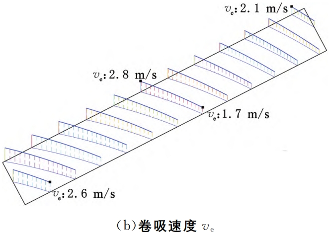
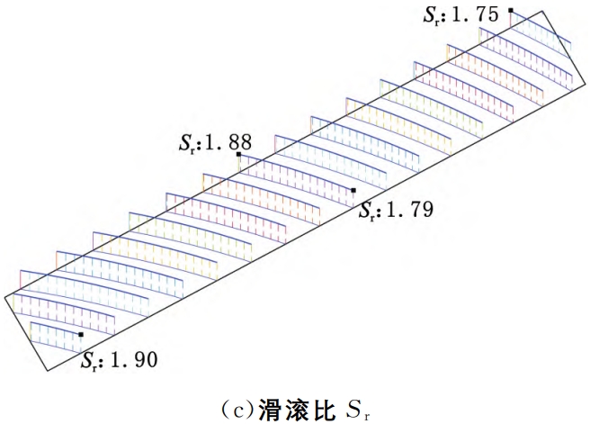
The distribution of the entrainment velocity and slip-roll ratio on the contact line is shown in Figure 6b and FigureAs shown in Figure 6c, the distribution of the HRRH tooth surface slip ratioIt is relatively uniform, and there is little difference between various parts of the tooth surface.This is the longitudinal sliding of the tooth surface.The effect of dynamic dominance is the meshing of the HRR gearsA significant feature of the transmission.
3. Contact point load calculation
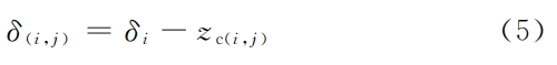
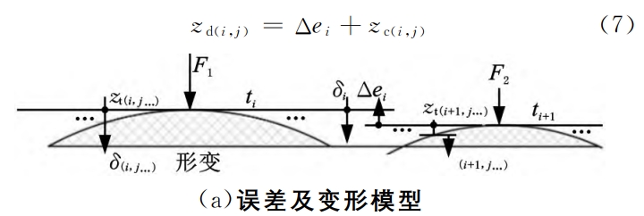
3.1 Bearing Contact Analysis LTCAFor any contact line, except for the trace point, the contact lineThere is a gap punikac in other positions.Assuming that under the action of load F,The total deformation of the tooth surface is δi, which is also the normal deformation of the trace point.The deformation of other units on a contact line is δi- zinc, obviouslyOnly the units at the position of δi≥웠 c will be in contact.From Figure 4, the gap between the rear tooth and the front tooth is Δei+1, and the rear toothThe contact condition is δi≥Δei+1.Assuming that the load is applied to 2 teeth(t1, t1+1)m units are responsible for the trace from t1 contact wireClick “Start Loading”, and the gap will expand from small to large.The current t1 is connectedThe unit on the contact wire deforms to

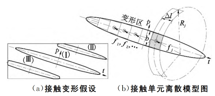
3.2 Contact Stress Calculation
Consider the tooth surface as a semi-space Hertzian point contact with infinite elasticityThe instantaneous contact deformation is generally an ellipse as shown in Figure 9a.(I).However, as the load increases, the contact deformation will exceed the tooth surfaceThe boundary has a distortion at one end (II) or at both ends (III), which belongs to finiteElastic space is not suitable for Hertzian point contact calculation.Therefore, the micro-The integral idea is to use finite cylindrical elements to fit the deformation area, that is,The deformation zone is subdivided into m sections with a width of Δl in the direction of the contact line t-tA cylinder, as shown in Figure 9b, can be seen as a radius at any positionThe contact between the cylinder of Rj and the plane.Assuming that the cylinder micro-segment ΔlIf m is small enough, then the three contact problems in Figure 9 can all be solved.The problem is solved by fitting a micro-segment cylindrical body.
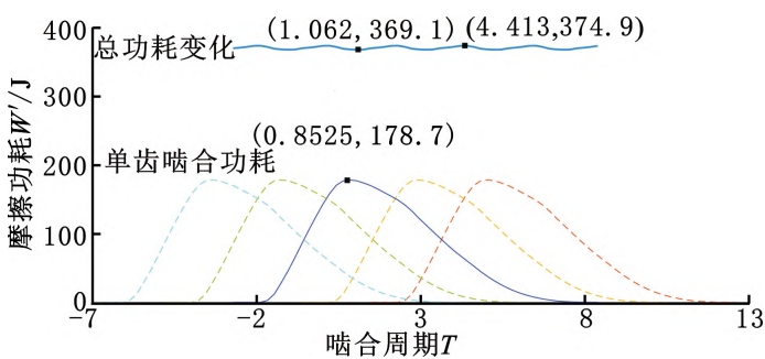
4. Calculation and analysis of tooth surface EHL friction power consumption
4.1 Calculation of minimum oil film thicknessThe line contact EHL model is easy to solve, but the contact line isThe curvature, entrainment velocity, and load parameters of the intended position are different, and the line connectionThe EHL model cannot be directly used.Use the contact shown in Figure 8bStress calculation unit subdivision EHL interface transforms point contact problemsFor micro-unit wire contact.
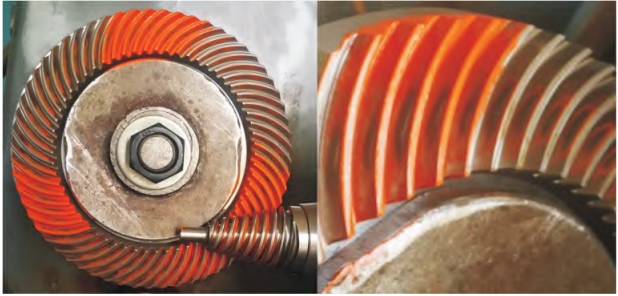
5. HRRH transmission efficiency test
5.1 Contact Quality InspectionFirst engage the 3:60 HRRH gear that is being processedQuality inspection to ensure compliance with the design standards for meshing quality.Figure 12shown as the contact spots left by rolling inspection of the tooth surface on the rolling inspection machine.FromThe contact spot observed on the convex surface of the large wheel is oval and located in the middle of the tooth surfaceOn the small end, there is no edge contact, which is similar to the result of the “easy-off” modification shown in Figure 2.The results comply with the inspection standard for contact spots of bevel gears.

6 Conclusion
Constitutive complexity of HRR gear meshing interface modelproblem, providing an easy-of-surface, LTCA analysis and tooth surfaceThe theoretical model and calculation process of EHL analysis avoid nonlinearityEquation system, partial differential equation solving and 3D finite element massive operationThe problem was verified through transmission efficiency tests, and the main conclusions wereAs follows:
(1) The easiness-off curve for complex HRR tooth surfacesSurface analysis, deformation coordination equation, contact line differential element method, canConveniently solve the geometric contact, motion, and mechanical parameters of gear teeth, making it easy to implementThe parameterization and programming of the current LTCA analysis.(2) For the problem of finite elastic spatial contact distortion on the tooth surface, a differential element method for contact lines was proposed, and the comprehensive EHL friction factor was integrated into the calculation model.solved the problems of load distribution calculation and EHL parameter solutionThe results show that the load stress on the tooth surface, oil film thickness, friction coefficient, and wear rate are all reduced.The distribution law of power consumption is analyzed.(3) The average value of HRRH gear transmission efficiency obtained from the test is79.45%, which is in good agreement with the theoretical calculation results.The average error is 0.2%, the maximum error is 2.8%, and the theoretical and experimental errors areThe difference is within the credibility range, which proves the HRRH gear meshing providedThe correctness of the efficiency calculation model and analysis method.