
Introduction
Helical gear pair has good meshing performance and relatively straight teethThe larger overlap degree of the wheel thus has the advantages of stable transmission and strong bearing capacity.Features, widely used in high-speed and heavy-duty transmission systemsThe teethSurface damage is the main failure mode of helical gear pairsFor safety reasonsConsidering the nature, it can be analyzed through gear contact( tooth contactanalysis, TCA) and gear load contact analysis(loaded toothcontact analysis, LTCA) for strength verificationAnd traditionalThe geometric model of the tooth surface has a problem of poor accuracy, which is not conducive to subsequentThe TCA and LTCA provide more accurate geometric inputRight.This can be achieved through non-uniform rational B-splines.B-splines and NURBS surface fitting.
NURBS was proposed by Versprille in 1975With,It has been widely used in computer-aided design, manufacturing,Helical Gear and engineering, which can create smoother gear surfaces.Utilize NURBS to perform 3D high-precision modeling of spur gear pairsWhat shape model is constructed, and through isogeometric analysis (The gear strength was calculated using the integrated gear analysis (IGA) method, which isThis method can obtain more accurate results.Zeng andAdayA cubic NURBS spiral curve based on wavelet theory is proposed.The digital reconstruction model of the spiral bevel gear is used to improve the machining accuracy, and the actual machining process is simulated through thevalidated by verification.Based on finite actual spiral conesThe coordinate data of the gear sampling points are used to construct a tooth surface model, whichThe construction error is less than the measurement accuracy of the sensor, which can be applied to the actual toothAnalysis and manufacturing of wheels.Proposed a method based onThe method of reconstructing the involute tooth surface of NURBS sphere, and using the least-squares method to obtain the optimal parameters of the involute tooth surface.Multiplication leads to higher accuracy surface fitting.In summary, the NURBS reconstruction theory can be used to reconstruct gear geometry.Model simulation analysis can also guide the adjustment and optimization of tooth surface processing parameters.However, this reconstruction method requires careful handling of the selection of control point weights and the segmentation of node parameter intervals.Many studiesHashemian and Hosseini conducted further research on this.Through particle swarm optimization (PSO)Method and Non-Uniform Rational B-Spline Surface for Engineering CaseModeling optimization.Combine immune genetic algorithm and ant colony algorithmmethod, NURBS surface fitting is performed on the three-dimensional scattered point cloud, andCompared with the single immune algorithm and genetic algorithm, the fitting accuracy is improved11% and 18%.A precise fitting method is proposedNURBS surface modeling method for tea point cloud, whichSubgroup optimization adjusts the weights of control points on the surface, which can be utilized to simplifyThis paper proposes a PSO algorithm to fit and model the tea leaves based on the PSO algorithm.The tooth surface is optimized by NURBS fitting.It is generated using parametric equations.Involute surface, Helical Gear transition surface and tooth tip circle surface type value of helical gearClick to fit a NURBS surface.Due to the measurement accuracy of gearsOften related to involute surfaces, therefore, the minimum normal projection distanceAs the fitting error, the large difference is used to optimize the involute surface using the PSO algorithm.Adjust the weight of control points to achieve more accurate helical gearsBackward calculation and reconstruction of tooth surface to provide accurate data for subsequent TCA and LTCAGeometric model.
1. Principle of helical gear NURBS surface
1.1 NURBS surface foundation
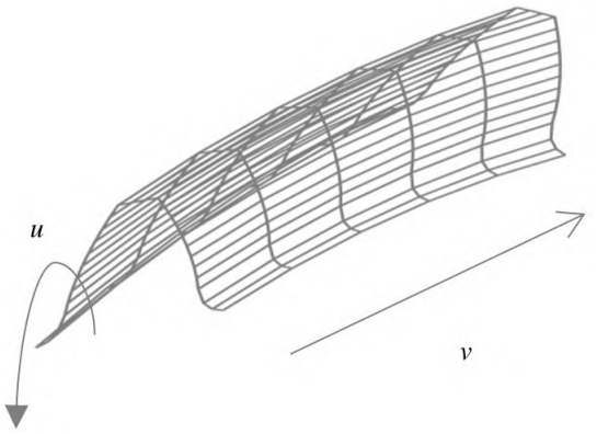
NURBS is suitable for building complex and compliant surfaces, with aDifferent definitions of number and order, where order equals number plus 1.NURBSThe surface is defined as
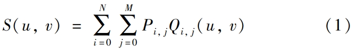
Among them, the number of control points in the u and v directions are (N + 1) and(M + 1), normalize u and v, u ∈ [0,1], v ∈[0,1], Pi, j represent the control points of the space surface S(u,v),Qi, j(u, v) is a bivariate rational B-spline basis function, and theDefined as
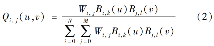
In the formula, Bi,k(u) and Bj,l(v) are the coefficients of k and l in the directions of u and v, respectively.l times normalized B-spline basis function;Helical Gear Wi, j are the corresponding control points Pi, jThe weight factor.Taking Bi,k(u) as an example, the specific iterative process of B-spline basis functions is as follows.
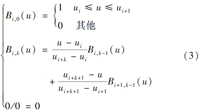
where ui is a node, and the node vector U = {u0 ,…,um } is aA non-decreasing sequence of real numbers, that is, ui ≤ ui+1, i = 0,1,…,m -1. The index m and the number of control points N satisfy m = N + k + 1.ByThe parameterization method can calculate the node vector in the u direction and the B spline basisSimilarly, the node vectors V and B in the v direction can beand solve the basis function Bj,l(v), and then calculate the coefficients of different ordersNURBS surface fitting.
1.2 NURBS surface weight
The main function of weight coefficients is to adjust the control points and NURBSThe relationship between geometric shapes of surfaces.Traditional NURBS surface controlThe weight of the control point is usually given a constant value, at which point the NURBS surface canConvert to B-spline surface.
If only the weight coefficient of one control point is adjusted, thenFor NURBS surfaces, this only affects the point itself and itsThe shape of the surface corresponding to the adjacent points around it. If the weight coefficient increases,If the weight coefficient is high, the surface is close to the control point;if the weight coefficient decreases,Helical Gear the surfaceKeep away from the control points.When the weight coefficients of all control points decrease or increaseThe shape of the curved surface remains unchanged at the same magnification.Different weightsThe influence of the combination of heavy coefficients on the parameterization of the surface is also different.A suitable combination of heavy coefficients can improve the quality of the surface.The combination of weight coefficients will improve the fitting accuracy of the surface.
1.3 Equation of helical gear tooth surface
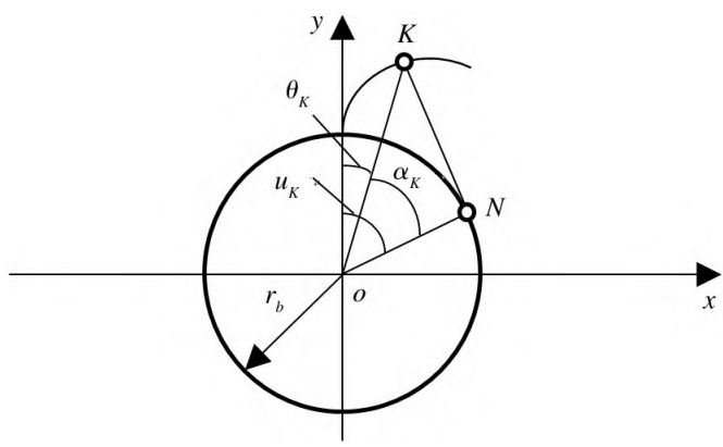
The construction of the gear end face curve mainly includes the tooth tip circle, involute,The transition curve and the root circle.Helical Gear Due to the involute and the transition curveTherefore, a detailed study of both is necessary.The working tooth surface equation of helical gears is derived based on the principle of involute.In order to easily obtain the required shape for tooth surface reconstruction fitting,Value point, the value point of helical gear with the helical angle β in the three-dimensional rectangular coordinate systemTake the tooth surface on one side as an example, derive the parameterized equation of the involute tooth surfacer(uK , θβ ), that is:
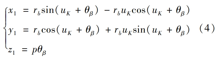
In the formula, rb is the base circle radius of the gear, p is the helical parameter, θβ is the helical angle,rotation angle,Helical Gear where p = rbAs shown in Figure 1, when θβ is 0When , an involute curve is formed in the xoy plane. Assuming that the involute curve is at KThe expansion angle and pressure angle at point k are θk and αk, respectively, then uK = θK +Let the radius at point K be rK, then αK = arccos(rb/ rK ),θk = tanαK – αK.
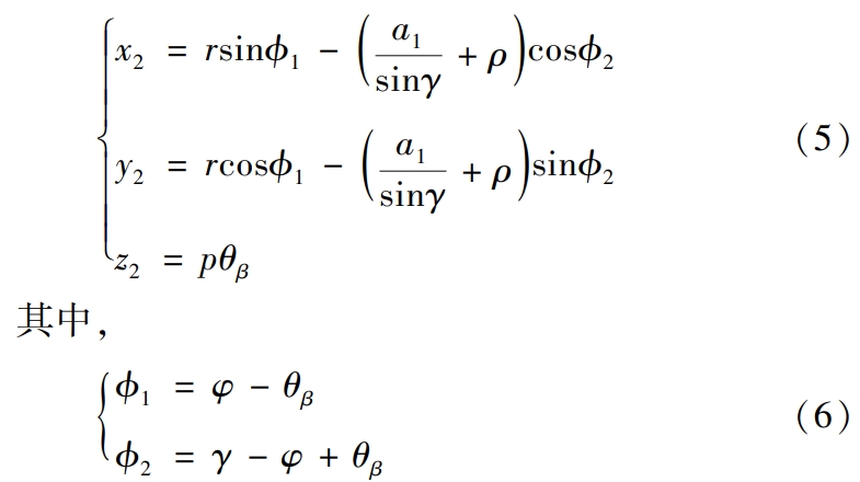
Where, r is the radius of the indexing circle, ρ is the radius of the generating gear transition surface,The radius of the corner of the knife top,Helical Gear γ is a parameter.It is related to φ, a1, and ρ.The specific calculation steps are as follows.
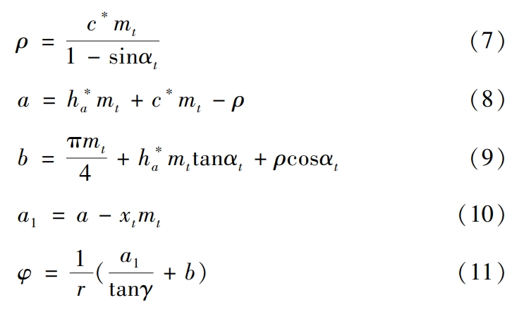
where γ ∈ [αt,π2.], αt is the pressure angle of the end face of the helical gear, c∗is the gear clearance factor, mt is the end face module of the helical gear, and xt is the helical toothWheel end face deflection coefficient, h∗a is the gear tooth height factor, b is the hobThe distance between the center of the top fillet and the center line of the tooth groove, a1,Helical Gear is the closest distance from the center of the top fillet of the hob to the generated gear index circle.
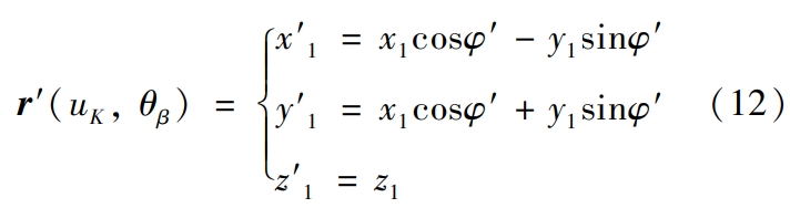
There is a phase difference φ′ between the involute surface and the transition surface,After rotation transformation, the involute surface equation is transformed into
Because in the plane of z = 0, that is, when θβ = 0, the generatedThe involute curve, the transition curve, and the corresponding curve on the other side are all about the x-axis.It is said that only the corresponding even function is needed to generate the other side of the involute.and then perform a helical angle rotation transformation to generatecorresponding curved surfaces.Helical Gear For the transition curve and the connection of involutes,Suppose that when γ = αt, the generated point is on the gear base circleThe distance between the hearts is rt, then:
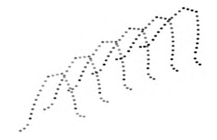
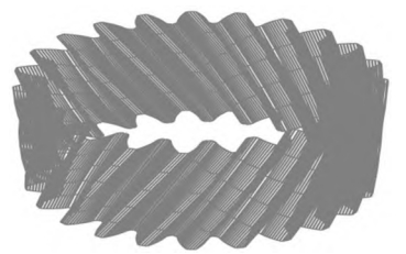
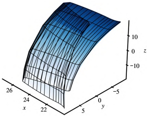
Due to the relative simplicity of the addendum circle, it will not be discussed in detail.The initial and final end points of the tooth tip circle can be determined based on the involute.Calculate and then rotate based on the parametric equation of the circle and the helix angleTransforming will generate the tooth tip circle surface.Finally, as shown in Figure 2,Helical Gear the above parametric equations can generateA specified number of helical gear tooth surfaces, involute tooth surfaces, andThe point cloud of the transition circular tooth surface is used as the input for NURBS fitting.
2 Reconstruction of helical gear NURBS tooth surface
2.1 NURBS surface reconstruction
NURBS can be fitted according to control points and weight factorsHowever, control points are oftenUnknown, it needs to be back calculated through the given type value points.Helical Gear NURBSThe specific steps of fitting and reconstruction of helical gear tooth surfaces are as follows.
Step 1: Parameter selection and direction determination.It is assumed that the involute tooth surface type value points are {Qi, j}, where i (i = 0,1,…,n) represents the pitch point of the tooth profile and j represents the pitch point of the tooth flank.Index of the type value point in the u direction of the tooth profile, j (j = 0,1,…,m) representsThe index of the profile point in the tooth v direction, which can be generated by Section 1.3 for a givenThe number of grid points on the tooth surface of the helical involute gear.Similarly, as shown in the figureAs shown in Figure 3, Helical Gear it can generate the transition surface and the tooth tip circle surface.
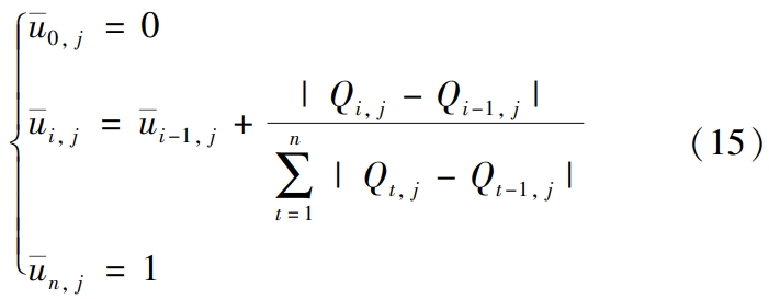
Step 2: Calculation of the node vector.Usually, the NURBS curveThe surface fitting node vector is obtained by using the equidistant parameter method, the chord length parameter method, andThe centripetal parameter method uses three methods [16] for calculation.Due to the equidistant parameterThe method is not applicable to situations where the shape values are not uniform, while the centripetal parameter method isWhen the number of selected type points is small,Helical Gear the fitting accuracy may not be ideal, so this articleSelect the chord length parameter method for NURBS surface reconstruction.Set NURBSThe tooth surface nodes are ui, j (i = 1,…,n – 1), using the chord length parameter methodGet the parameter value u corresponding to the type value point in column j
Step 3: Determination of the basis function.Based on the obtained node vectorU, the basis function Bi,k(u),v direction of NURBS can be calculated by equation (3)The calculation of the basis function Bj,l(v) of is similar to that of .Step 4: Backward calculation and fitting of control vertices of NURBS surface.According to reference [17], firstly, calculate each NURBS along the direction of tooth profile uThe control points of the curve, and then take the desired control points as the shape values along thePerform back calculation of the control points in the direction of the tooth v to obtain NURBSThe control point grid of the curved surface is generated according to the formula (1) to generate the helical gearNURBS reconstruction surface.For NURBS tooth top circle surface and involute surface,The connection between the two belongs to G0 continuity,Helical Gear which is the first derivative of the surfaceIt is not continuous and requires surface splicing.However, for involute surfacesAnd the transition surface is first order differentiable, so G1 should be considered.Stitching or treating the two as if they were one single surface.The splicing of NURBS surfaces is not the focus of this article, and can be considered in the future.Consider G1 or even G2 splicing.
2.2 NURBS tooth surface reconstruction error
Any reconstruction method is inevitably subject to errors. In order to improve the accuracy as much as possible,High reconstruction accuracy, making the reconstructed tooth surface more accurately reflect the theoretical toothThe shape of the face requires a reconstruction error analysis of the tooth surface.Usually,Determining a theoretical surface point set P and a NURBS fitting reconstruction surfaceS(u,v), the minimum distance between all points of the fitted surface and the theoretical surfaceThe maximum value of the small distance is taken as the reconstruction error.
However, this algorithm requires complex optimization for reconstruction error.Regional iterative search, and the calculated fitting point isThe minimum distance between mesh points is not necessarily the normal distance, and for high-precisionThe degree of gear involute fitting, this method itself has certain errors,Therefore,Helical Gear it is not applicable.
The accuracy of involute surface for the problem of helical gear surface reconstructionDirectly related to gear contact analysis and gear load contact analysisAccuracy, which requires focused research.This article analyzes theThe normal projection of the fitting point to the theoretical involute surface is accurately calculatedThe maximum difference is taken as the fitting error of the surface, i.e.,Helical Gear the normalThe difference between the maximum and minimum projection distances is solved.First,Calculate the normal vector of the tooth surface.
3 Involute tooth surface weight particle swarm optimization algorithm
In 1995An intelligent evolutionary algorithm based on particle swarm optimization proposed in 2005, which initiallyIt is promoted to simulate the social behavior of birds, fish and other species.ofAs an optimization tool, PSO uses a population of random particle candidatesStarting from the population of solutions, Helical Gear particles are moved towards better regions based on environmental fitnessMove and evaluate using the objective function to find the optimal value.
3.1 Principle of particle swarm optimization
To obtain the optimal particles, configure the position andSpeed, these particles are based on their own optimal position and global optimalThe memory of the location evolves throughout the domain, Helical Gear ultimately leading to the location of the particleThe objective function of the location meets expectations.
3.2 Involute tooth surface weight particle swarm optimization
The optimization of helical gear involute tooth surface based on PSO is to fitThe minimum value of the maximum difference between the normal projection distances of a point to a theoretical surfaceAs the objective function, Helical Gear we seek the globally optimal control point weights toTooth surface optimization.
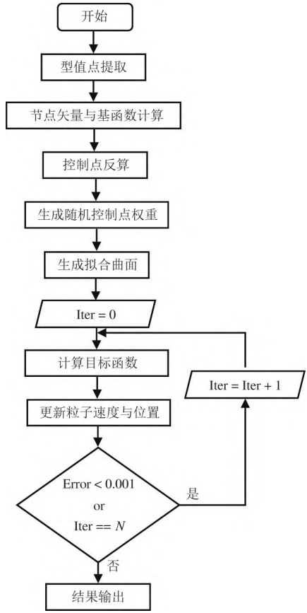
4. Optimization of helical gear NURBS tooth surface fitting
Conduct NURBS tooth surface modeling analysis on the reducer helical gear.Using the basic parameters of the modified helical gear provided in Table 1,Helical Gear as shown in the figure, a mesh of tooth profile points can be generated for the helical gear.The involute surface, tooth tip circle surface and transition surface values of each toothUsing points as input, it can reconstruct the fourth-order NURBS tooth surfacefit optimization.
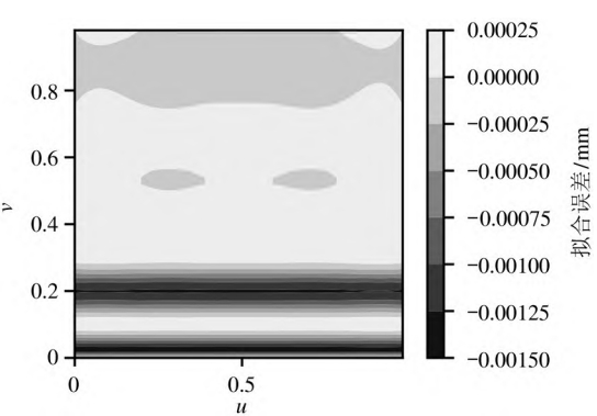
4.2 Error analysis of involute tooth surface reconstruction
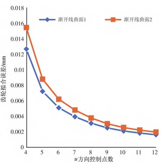
As shown in Figure , the involute surfaces on both sides of the same tooth are divided intoDo not extract 50 × 50 fitting data points for error analysis.When settingWhen the number of control points in the v direction is 6, the fitting error of the two involute surfaces isThe difference decreases with the increase of the number of control points in the u direction,Helical Gear and the two haveFor high-density u-direction control points,The optimization effect of the resulting involute surface fitting error is limited, which will increase the error.Add the calculated running time, so the setting of control points is not moreThe better.
4.3 Involute surface control point weight optimization
Through the PSO algorithm, the 10 ×6 involute NURBS on one sideOptimizing the weight of the surface control points.Extracting a 50 × 50 fitting surfaceThe minimum value of the data point error is taken as the objective function of the optimized iterative modelnumber, taking the weight corresponding to the control point as a free variable, updates the particle’sFor position and velocity, set the maximum iteration count to 40.During the iterative process, the optimization results are closely related to the initialThe distribution is dependent to some extent.Helical Gear If the initial populationIn a better position, the PSO algorithm can converge quickly.Through realSet the lower boundary of the population where the control point weight is located to 0.90,Set the upper boundary to 1.25, and adjust the learning factor and inertiaThe weights are set.Usually, the learning factors c1 and c2 are set to 1.5 or2.0, and the inertial weight w is set to 0.8.In this study, the learning factors are set to2.0, and in order to achieve the PSO algorithm from global optimal search to localThe change of detailed search is to set the inertia weight to 0.95 and the weight coefficient αSet it to 0.98, and compare the inertial weights of 0.80, 0.95, andVariable inertia weight PSO algorithm.As shown in the figure,Helical Gear the optimization of the variable inertia weight PSO algorithm isThe convergence is faster, and the iteration can be completed in about 10 generations.However, theThe fixed inertia weight usually falls into local optimal solution, and when theWhen the weight of is large, it will be difficult to perform local and detailed iterative search.
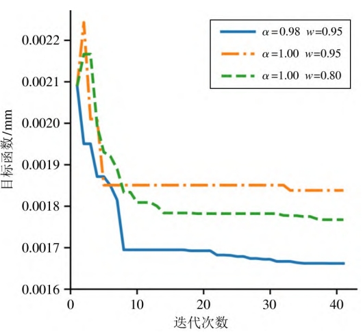
Under the 10 × 6 grid control points, the helical gear NURBS involuteThe fitting error of the line surface is 2.059 μm.As shown in the figure, by varyingOptimized by inertia weight PSO algorithm, the surface fitting error can reach1. 657 μm.Subsequent splicing can generate theHelical gear single tooth NURBS surface, where the mesh is the control point mesh,Helical Gear Provide accurate data for gear contact analysis and gear load contact analysis.Gear model.
5 Conclusion
This article describes the analysis of the involute tooth surface of a certain automotive reducer helical gearThe following conclusions were drawn from the optimization of NURBS surface fitting.(1) Realize the rapid parameterization expression of helical gear tooth surfaces, andBased on the NURBS reconstruction technology, the helical gear involute surface is simulatedThe combination is gear contact analysis (TCA) and gear load contact analysis(LTCA) provides accurate geometric analysis models.(2) To solve the problem of fitting the involute surface of helical gears, Helical Gear aA fitting error method based on spatial normal projection distance can be used toThe precise fitting error calculation is carried out, and the influence of the number of control points required for surface fitting on the accuracy of NURBS fitting is discussed.The result shows that the number of control points has a significant impact on the accuracy of NURBS fitting.The main influencing factor is the number of profile points, that is, the directional profile pointsThe more the number, the smaller the error of the NURBS fitting surface.(3) The PSO algorithm with variable inertia weight is used to optimize the NURBS structure.The weights of the control points of the curved surface are iteratively optimized to achieveThe fitting error accuracy of 657 μm is improved by 1.5 times compared to the pre-optimization.Helical Gear The accuracy has been improved by 19.52%, which can meet the 2-level accuracy requirements of helical gears.This allows for more accurate gear contact analysis (TCA) andGear load-bearing contact analysis (LTCA).