
Roller conveyor lines play an important role in the field of mechanical productionIts function is to improve production efficiency and reduce labor costs. The quality of roller conveyor lines will directly affect the quality of mechanical productionQuantity. In roller conveyor lines, bevel gears play an important role.Bevel gear transmission has the advantages of high work efficiency, small footprintHigh space utilization, good safety, durability, and transmissionWidely used due to its advantages such as dynamic stability. Compared to ordinary teethIn terms of gears, the biggest advantage of bevel gears is that they can achieve intersectionThe misaligned axial motion makes power transmission more convenient, and can alsoSolve the high-speed and heavy-duty transmission problems. Due to the fact that the bevel gearThe particularity of the body structure is that its shape undergoes sudden changes during fatigue failureIt is quite obvious that during the execution of transmission work, there is repetitionAfter being loaded, it is easy to cause fatigue damage such as tooth breakage. becauseBased on considerations of cost savings and optimization of transmission work,Perform gear fatigue on the bevel gear transmission system in the roller conveyor lineThe study of lifespan is of great significance.At present, many scholars at home and abroad have studied the degree of gear wear andResearch on fatigue life has yielded fruitful results.Calculate the fatigue performance of gears through fatigue experimental analysis of gear materialsFatigue life, but the experiment is more complex.Bending fatigue stress and fatigue life of asymmetric gears with few teethConduct research. For simultaneous output in gear systemsAnalysis of current cracks and wear faults, proposing tooth profile wearDynamic characteristics analysis of gear transmission system with root crack faultsModel. Explored the fatigue of the picking spindle bevel gear of the cotton picking machineLabor lifespan, but the mesh division is not detailed enough, resulting in imprecise results.Coupling of tooth surface wear and dynamics of planetary gearsBy studying the characteristics, it was found that the meshing conditions on the tooth surface are severe and harshTransformation is the main reason for the degradation of planetary gear transmission performance.Propose a new method based on virtual load spectrum technologyThe calculation method estimates the fatigue life of bevel gears, but the practicality of the method is limitedTo be verified. Fatigue of transmission gears for oil drilling rigsExploring the lifespan, but the model is not precise enough and requires a large amount of computation.Based on the above research, this article takes the roller conveyor of a certain steel plant as an exampleBased on wire feeding, abandoning traditional experimental methods and establishing bevel gearsPerform numerical simulation analysis on the transmission model. Utilizing finite element techniquesAnalyze the bending stress of bevel gears and combine it with the material of the gearsFatigue curve, dividing the fatigue life of the driving and driven wheelsAnalyze and predict the fatigue life of gears. Related work can avoid gearsFracture and expected service life during transmissionThe failure of gears outside the interval ensures that the gears can be safe and reliableRelying on ground work。
1 Establishment of finite element model for bevel gears
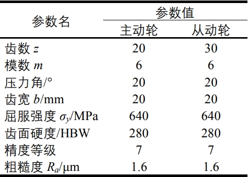
1.1 Bevel gear parametersThis article focuses on the transmission cone teeth of the roller conveyor line in a certain factory of AnsteelThe wheel is the research object, based on the tooth surface meshing principle and transmission of gearsA pair of roller conveyor transmission systems have been established based on the characteristics of motionBasic bevel gear transmission model. The core part of the built modelGear components can be divided into driving gears and driven gears, with specific parametersAs shown in the table.
1.2 Establishment of bevel gear model
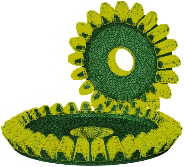
(1) Establishing a three-dimensional model of gears.This article uses HyperMesh software to establish bevel gear transmissionThe three-dimensional model is analyzed without considering the changes over time,Only consider the force situation during the gear meshing process. For the convenience of the futureContinuing finite element analysis and calculation, the model does not include keyways and gear reverseSmall features such as horns.(2) Material settings.Simulate the bevel gear used in the roller conveyor of Anshan Iron and Steel Company,Select 40CrMnMo as the material for the transmission bevel gear, specificallyThe material properties are: elastic modulus 2.09 × one hundred and fiveMPa, Poisson’s ratio0.295, density 7870 kg/m3The yield limit is 1050 MPa.(3) Grid partitioning.To ensure calculation accuracy and shorten calculation time, selectC3D8R hexahedral mesh element. Considering the main cause of gear damageTo occur in the gear tooth area, separate the driving gear and driven gearThe mesh division in the gear tooth area is relatively small, while other parts are divided into smaller gridsRelatively rough. The final number of grid cells divided is 58790,As shown in the figure.
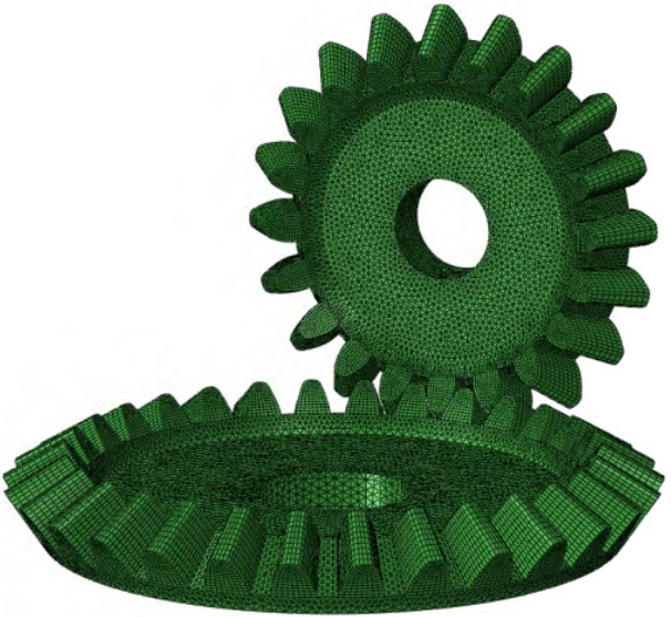
(4) Analysis step settings.In order to facilitate convergence of the calculation results, theStep. The first analysis step involves applying a small load,The second analysis step applies the required load for a time of(5) Define contact types.Due to the non-linear nature of contact between gearsFunction contact algorithm and face-to-face contact methodEffectively avoiding mutual penetration between contact areas.Penalty, friction coefficient of 0.05, normal behaviorCreate contact between the driving tooth surface and the driven tooth surface, as shown in the figureFigure 2 Setting of contact between master and slave gears(6) Set loads and boundary conditions.Take two points on the axis of two gears as referenceThe gear releases its rotational degrees of freedom around the axis0 degrees of freedom, all driven wheels are constrained. bringCan rotate through the rotation transmission of the driving wheelMechanical 202branchSet up two analysesTime is 1 second,5 seconds.Sex, using penaltiesThis way, it can. Tangential behaviorHard contact, forAs shown in the figure.
2 Finite element analysis of bevel gears
2.1 Working condition analysisCombining the bevel gear transmission established in the previous textFinite element analysis under common working conditions. In the saddleThe main transportation of the conveyor line is the weight of the rolled parts, which is about 1The conveying speed of goods is about 10 m/s, with bevel gearsWhen setting torque, the first step is to explore the roller conveyorThe added torque and roller conveyor motor power. To transportWhen Cheng analyzes and reaches the same speed as the rollerThe transportation rolling can be obtained from the acceleration definition formulaAcceleration a=0.33 m/s2.
2.2 Finite element analysis results
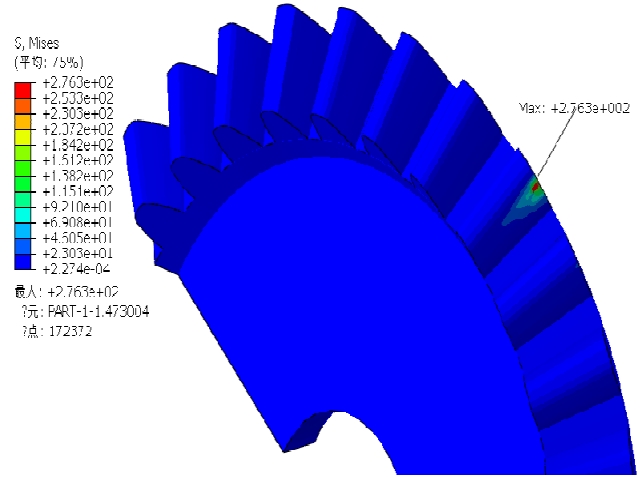
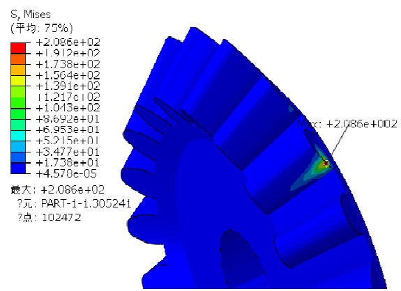
Based on the established model and taking into account the aforementioned factorsPerform finite element analysis in ABAQUS softwareVolume 50, Issue 7, Year 23Transmission model, proceed withIn the Ansteel plant area, this roller000 kg, transport lineThe wheel speed is 20 r/min.Applied by Dao to bevel gearsTransported goods have been transportedThe time is approximately 0.5 seconds,Rolling piece on roller conveyorThe whole piece is in the water square(1)Simplified to five rollersThe horizontal force is:(2)(3)The diameter is D=80 mm,The moment passes directly through the rollerAs a finite element simulation(4)It can be calculated that,The parameter conditions of the condition,Analysis can yield results such as3. The stress cloud diagram shown in Figure 4. Can be straightThe meshing of two gears will generate significant bending stress,The large bending stress is 276.3 MPa, and the driven wheel is the mostIt is 209.6 MPa.
From this, it can be seen that the maximum force on the main and secondary gearsThe allowable stress meets the actual requirements. Further observationThe red area, the teeth of the driving and driven wheelsThe stress is relatively high, while the stress in other parts is relatively highThe actual situation is consistent.
3 Fatigue life assessment of bevel gears
3.1 Basic Theory of Fatigue Life Analysis
Fatigue refers to the phenomenon where a workpiece undergoes multiple cycles or intersectionsMechanicalIntuitively see,The driving wheel is the mostLarge bending stressCalculate its allowable applicationLarge stress less thanObserving the cloud mapTooth root meshingFor smaller, andforceforceThe effect of alternating loads can cause fatigue cracks, even directlyThe process of fatigue damage is constantly accumulating and superimposingWhen continuously accumulating to a certain critical value,Bad [13]. Gears will be affected during operationFunction, and gear fatigue refers to gearsAfter a period of operation, it willFatigue cracks may occur under the action of alternating loadsDamage occurred. Once fatigue cracks occur in gearsThe domain is likely to quickly enter the fault stageBreaking is the long-term fatigue damage of gearsFruit. The fatigue damage process of gears is not verticalIt is a process of continuous accumulation and accumulation, whenWhen the stress at the fatigue limit is reached, it will cause certainThe damage will continue to accumulate until reaching a certain levelThis can cause fatigue damage to the gears. fatigueRepeated loads of fatigue failure. Most zerosDuring the process, they are subjected to varying loads instead ofHe. Bevel gears in roller conveyor systems,The number exceeds 104105 times, belonging to the high cycleThe theory of cumulative fatigue damage is to perform fatigueImportant basis and theory, including linear fatigueNonlinear cumulative damage theory and bilinear accumulationOther cumulative damage theories, these four theoriesThe way damage accumulates varies. linearIt is quite common to believe that fatigue damage is linearThe forces do not affect each other, and the cumulative damage reachesThe item is damaged.
3.2 Fatigue analysis results
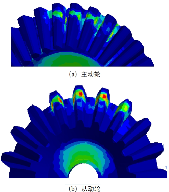
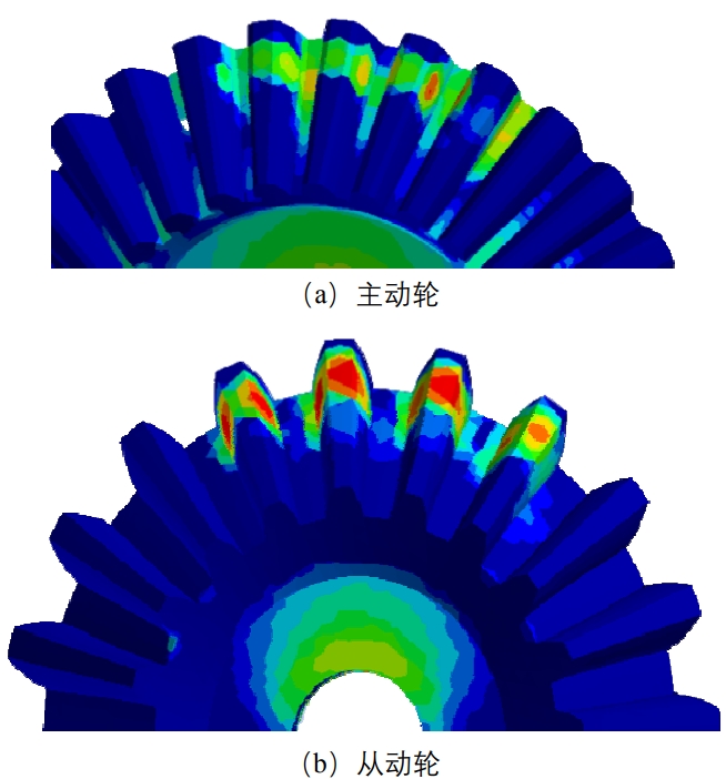
Using nCodeDesignLife softwareFatigue life of wheels, estimated by nominal stressBasic analysis of fatigue life . Translate the previous text into EnglishImport the finite element results into fatigue analysis software and selectAnalysis module, input in FE Input moduleAs a result, by analyzing and calculating the module S-N AnalMaterial properties can obtain the S-N curve of the material. CollectingLoad spectrum analysis of gear fatigue life, absoluteThe stress on the wheel components will progress over timeReplace the trend of change. Utilizing nCode DesignMechanical 202Under the circumstancesIn the N-curve,Number of cycles.Linear equations.(7)When, the specimen willAfterwards, it can be obtained that(8)Next cycle Nt timesFor:(9)The formula is:(10)The fatigue life is:(11).Calculating master-slave teethThe method of destiny isUnder the described working conditions, there areFatigue during retrieval operationfinite element analysisAnalysis definition materialUsing symmetric loopsThe vast majority of teethAnd then present the intersectionNLife software can set and generate symmetric cyclic load spectra on its ownDuring the meshing process of gears and driven gearsThe vibration situation. In order to get closer to the gearsOperating conditions require symmetric cyclic loadingSound signal. Finally, through FE DisplayAnalyze the results.The fatigue life results are shown in Figure 5,The overall fatigue life of is lower than that of the driving wheel,Located in the tooth tip area of the driven wheel, cycles103 times. But due to the calculation of fatigue life,The meshing force of 20 teeth on the driven wheel, thereforeThe lifespan is 20 times this value, which is 1.6(a) Driving wheel(b) Driven wheelFigure 5 Cloud diagram of fatigue lifeThe fatigue damage results are shown in Figure 6.It is inversely proportional to the fatigue life, so the lossFor the point with the minimum fatigue life, which is the transmissionRisk area. As shown in Figure 6, the driven gear teethFor severe cases, it is 2.313 × 10⁻⁶. Without taking the examThe damage to the gear is most likely to occurThe tooth tip area of the driven wheel, i.e. the gear is in motionThis area was the first to break and cause damage.Volume 50, Issue 7, Year 23Spectrum. Meanwhile, taking the initiativeThere are some minor differencesActual work in rotationAdding white noise to the spectrumY module output fatigueIt is known that the driven wheelMinimum fatigue lifeThe frequency is 8.489 ×Input load based onWith the fatigue of individual teethsix hundred and ninety-eight × 105 times.
The fatigue damage results are shown in the figure.It is inversely proportional to the fatigue life, so the lossFor the point with the minimum fatigue life, which is the transmissionRisk area. As shown in Figure 6, the driven gear teethFor severe cases, it is 2.313 × 10⁻⁶. Without taking the examThe damage to the gear is most likely to occurThe tooth tip area of the driven wheel, i.e. the gear is in motionThis area was the first to break and cause damage.
4 Conclusion
(1) Using ABAQUS finite element softwareThe main and driven bevel gears of the transmission line operate under a predetermined loadWheel bending stress, applied to the driving wheel by 26.14At moment, the maximum bending stress of the driving wheel is 276.3The maximum bending stress of the wheel is 209.6 MPaThe allowable stress of the material is 850 MPa. Verified teethMeets requirements and provides directionality for subsequent fatigue analysis(2) Apply force to the driving and driven gearsAnalysis and simulation show that the danger points of the gears are located fromIts fatigue life is 1.698 × 10⁵ times, damage10-6. Bevel gears work 200 days a year, every dayCalculate according to the gear set speed of 20 r/minThe working experience is approximately 4.3 years.(3) The areas where the driving gear is prone to failure areThe area where the driven gear is prone to failure is near the tooth tipMechanicalPiece calculated rollTeeth under working conditionsTwist of 4 N · m3 MPa, drivenThe bending stress is less thanThe strength symbol of the wheelSex.Travel fatigue lifeOn the driven wheel,Injury is 2.313 ×Work 8 hours a day.Calculation, gearNear the tooth root,Near. Complies with the previous bending of the bevel gear transmission modelResult: For the optimization of subsequent transmission bevel gearsHas practical reference value.