
Gear transmission is widely used in machinery, transportation and other fields.The operating efficiency and service life are largely determined by the lubrication of the gearbox.Slippery performance, especially in harsh conditions such as low speed, heavy load, variable load, and impactUnder normal conditions, gears are often in dry friction or boundary lubrication state,Therefore, optimizing the gear lubrication design and improving the lubrication performance are important for improving the gear life.It is of great significance to improve the load-bearing capacity and extend the working life of the wheel.It is recommended to use EHL analysis as a tool for improving the performance of the gear.An important part of wheel design.
In traditional gear engineering design, it is usually based on mechanical manualsKnowledge and engineering experience to determine the accuracy of gear pairs and the selection of lubricating oil,The thickness of lubricating oil film under load conditions has not been reasonably calculated.Calculate.If considering the meshing of gear pairs, ensure that there is sufficient thicknessThe lubricating oil film completely separates the gear working surface, which can avoid toothDirect friction between the surfaces ensures the lubrication performance of the gear teeth and prevents lubrication failure.In recent decades, scholars at home and abroad have conducted research on the thickness and lubrication of gear contact oil film.Extensive research has been conducted on slip state.Since Martin K F introduced the Reynolds equation and other elastohydrodynamic lubricationThe theory of EHL has been applied to the analysis of gear lubrication problems, and after severalIn the past ten years, it has been continuously developed and improved.Wang Youqiang, Wang Fahui and others in ChinaThe dynamic minimum oil film thickness is solved for the tooth through the Reynolds lubrication equationEngineering design for wheel lubrication;Zou Yujing, Jian Guangxiao, Yuan S HElastohydrodynamic lubrication theory-based coupling of gear dynamics and elastohydrodynamic lubricationThe dynamic oil film rigidity and other issues were studied.
In recent decades, gear lubrication design has been mainly based on Dawson HigginThe minimum oil film thickness formula of Sen was used for calculation, and many scholars analyzed it.The influence of gear transmission parameters on the minimum film thickness.AnalysisThe influence of pressure angle on the EHL of gears is analyzed.The parameters that form the dynamic pressure oil film of the gear (the entrainment speed and the equivalent curvatureradius) to determine that the minimum oil film occurs at the root of the pinion gearand the position of the meshing point with the tooth tip of the large gear;analyzed the gearThe influence of the secondary modulus, pressure angle, and tooth width coefficient on the minimum oil film thicknessThe minimum oil film thickness on the meshing line is established as a function of theTime-varying model of number change;analyzed the relative slip of gearsThe variation law of dynamic speed along the meshing line, and the geometric parameters of gearsThe influence on the minimum oil film;Considering various factors on theThe influence of small oil film and the application of numerical method to select lubricant viscosity;Xiao Xin, Zhao Jingjing, Jian Guangxiao, etc. have conducted research on the elastic lubrication of the modified gear system.has done a lot of useful work on the sliding problem, revealing the relationship between gear pair modification andThe relationship between oil film pressure and thickness.
In the complex meshing process of gears, the load and relativeBoth the sliding speed and the geometric parameters of the gear pair vary with the position of the meshing line.There is a large amount of sliding during meshing near the tooth root or tooth tip, so the thickness of the oil film is also complexly changing, and the research on gear lubrication tends to be more and more detailed.Step by step to improve.When calculating the normal load distribution of a gear pair,Both use simplified calculations, directly dividing the normal load by 1/3WThe normal load at the beginning of the double-tooth meshing area is 1/3W, and the double-toothWhen alternating with the single tooth pair meshing area, the normal load is 2/3W, and the single tooth pairThe load in the meshing area is W, which is affected by factors such as the degree of coincidence and the displacement coefficient.The influence of this simplified algorithm on the actual meshing force distribution on the meshing lineThere are significant discrepancies, and calculating the load on the tooth surface based on the precise tooth profile will result inreflect the actual distribution of meshing force.It is firmly believed that the minimum oil film occurs on the pinion gearThe position of the meshing point between the tooth root and the tooth tip of the large gear, as well as similar conclusions, are:As the meshing point moves towards the tooth tip of the driving wheel, the minimum oil film thickness graduallyIncrease, these conclusions are used as a reduction drive within a certain transmission ratio rangeIt is appropriate, but as a general conclusion for gear transmission, it is worth discussing.In fact, based on accurate tooth profile modeling, the minimum oil film curve is drawnWhen the transmission ratio is close to 1, the gear pair coincidence degree is not very high andWhen using positive transmission, the meshing point and the disengaging point of the gear pair are far away from the theoretical meshing point.The minimum oil film position at the joint end will be in the middle single tooth meshing area.The minimum oil film thickness near the meshing node is close to the oil film on the meshing lineThe average level of thickness, so in general, theThe thickness of the small oil film is the benchmark for judging the lubrication state of the gear.Of course, when using a large transmission ratio or small gear in the gear pair,In the case of small or even negative tooth profile changes, the tooth roots of the pinion and the teeth of the gear wheelThe top meshing point is indeed the point of minimum oil film thickness, which can be used as the design point.Consider the focus.Starting from establishing the gear pair meshing model, combined with the gear lubrication machineand analyze the rule of the relative sliding speed of the gear changing with the meshing line,Further analysis of the relationship between the equivalent radius of curvature and the entrainment velocity on the meshing lineThe law of transmission ratio and modification coefficient change.Based on Dawson HigginsonTheoretical calculation and analysis of the minimum film thickness for transmission ratio, modification coefficient, pressure drop, and film thickness distributionVariation of minimum film thickness of gear meshing with transmission parameters such as force angle and center distanceThe influence of oil film thickness was analyzed through Matlab GUI programming to draw the oil film change curve.judge the lubrication performance and state of the gear based on the relationship between the oil film thickness and the friction coefficient,And applied to the case calculation analysis for gear lubrication design workersFor reference.
Relative sliding analysis of gear pair
The mechanism of gear lubrication: During the process of gear transmission, lubricating oilFill between the meshing tooth surfaces and form a continuous dynamic pressure oil film toDirect contact and friction of the meshing tooth surface, reducing tooth contact fatigueAt the same time, there is rolling friction and sliding friction between meshing gear teeth.Damn, rolling friction is beneficial to the operation of the oil film, while sliding friction can affect lubrication in two ways: 1. Sliding friction drives the flow of oil film,Reduce the probability of pitting corrosion on the tooth surface; ②reduce the risk of tooth failure under high load conditions.Sliding friction can easily break the oil film, causing tooth surface wear and tear.scratches and even gluing.Therefore, the lubrication performance of gears and the meshing processThe sliding speed is related to the scrolling speed.When gear transmission, the two gear teeth will not only make pure rotation at the meshing node,In addition to rolling, there is relative sliding between the two tooth profiles at the remaining meshing points.Move.
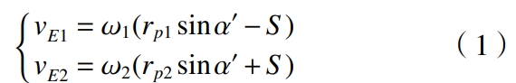
Wherein, and are the angular velocities of the two gears;is the pressure angle of the pitch circle;rp1 and rp2 are the pitch radii of the two gears;S is the distance from node P to the meshing pointThe distance of E, during the process of circular engagement, S corresponds to the actual engagement lineThe change of the position of the internal gear point E in B1B2, where B1 and B2 are the gear pairsEngagement and disengagement points.
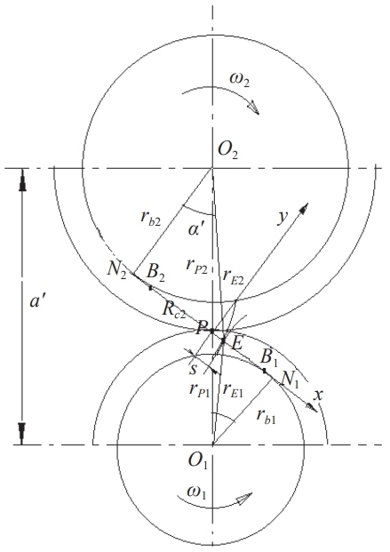
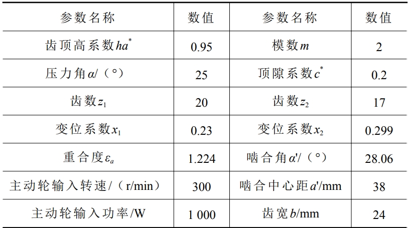
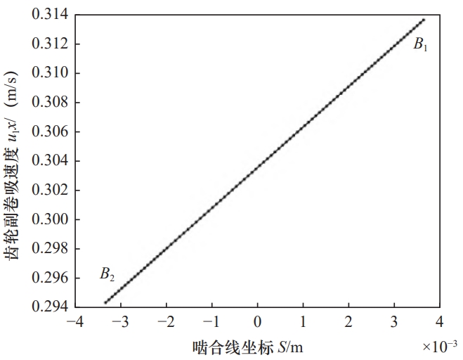
Take the meshing gear pair of the sun gear and planet gear in a planetary system as an example(See Table for gear parameters), calculate the relative sliding speed vH along the meshing lineThe change curve of the combined line is shown in the figure.
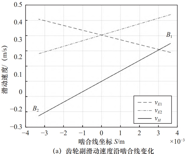
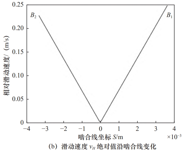
As shown in Figure 2a, the sliding speeds vH, vE1, and vE2 areThe line of the joint is linear;the speed vE1 of the large gear z1 is determined by the meshing pointThe point of meshing gradually increases, while the speed vE2 of the pinion gear z2The point-to-engagement point gradually decreases;when the nodes are engaged, the speed of the two gear teethThe degree is the same, and the node sliding speed vH is zero.Figure 2b shows the variation of sliding speed vH along the meshing line with absolute valueThe absolute value of sliding speed vH is in V shape, and the gear pair is meshingThe sliding speed reaches when the meshing point B1 and the meshing point B2 of the line are engagedThe top value.From the above analysis, it can be seen that the gear pair is meshing near points N1 and N2.When the relative sliding speed reaches the peak value, the gear optimization setting isTo avoid the increased wear of the gear pair tooth surface, measures should be taken toThe control gear pair actual meshing line endpoints B1 and B2 should be as far away from the meshing point as possible.The limit position points N1 and N2 are combined.
Elastohydrodynamic lubrication analysis of gear pair
According to the theory of elastic fluid lubrication, the minimum oil film for gear transmissionThe thickness is calculated using the Dawson-Higginson formula:
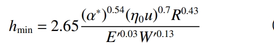
Where: ∗ R is the equivalent curvature radius of the gear at the meshing point;is the lubricationOil viscosity coefficient, m2./N;E′ is the equivalent elastic modulus of gear material;η0 is the dynamic viscosity of lubricating oil, Pa·s;u is the gear pair at the meshing pointThe speed of the gear;W’ is the gear’s load per tooth widthThe load.When calculating the lubricating oil film using equation (5), the gear meshThe values of the parameters R, u, and W’ are the ones that need to be focused on and analyzed.
equivalent radius of curvature
According to the theory of elastohydrodynamic lubrication, the equivalent curvature of the meshing point of the gear pair isThe ratio radius is the equivalent radius of curvature of the two contacting cylinders, with large and small teethThe curvature radii of the tooth surfaces of the wheel at the meshing point E are R1 and R2, respectively.Then the formula for R is
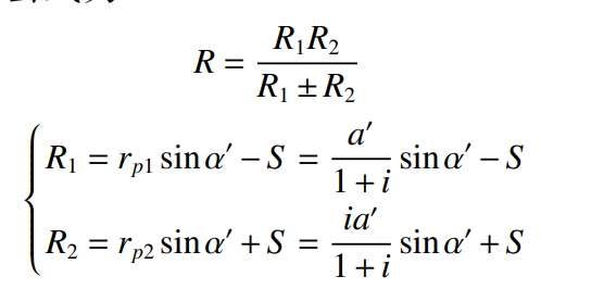
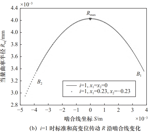
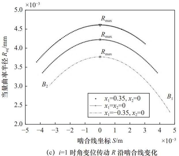
When the gear pair is engaged in high-modulation transmission, the transmission center distance a’ is notThe gear pair transmission engagement line N1N2 remains unchanged, as shown in Figure 3b.It is shown in the figure that x1>0, x2<0, and the actual meshing line B1B2 is along the direction of N1N2 to N2.When the radius R of the parabola is moved towards the end, the meshing lineSliding in the negative direction of coordinates, where the point position remains unchanged and remains at the nodeAt P, the negative deflection gear tooth root meshing point B2 is the equivalent radius of curvatureThe smallest point.When the gear pair is an angular modified transmission, the transmission center distance a’ is causedChange, positive transmission will make the center distance a’ larger, equivalent curvature radius ROn the contrary, negative transmission will make the center distance a’ smaller, and the equivalent curvatureAs the radius R becomes smaller, the positive (negative) modification of the gear will cause the end of the R curve toPoints B1 and B2 are far away from (close to) the end points N1 and N2 of the engagement line, as shown in Figureas shown.
induction velocity
From the above analysis, the velocity of the two-wheel tooth contact surface relative to the meshing point E is u1 = vE1 and u2 = vE2, then the surface entrainment velocity of the wheel tooth isDegree is
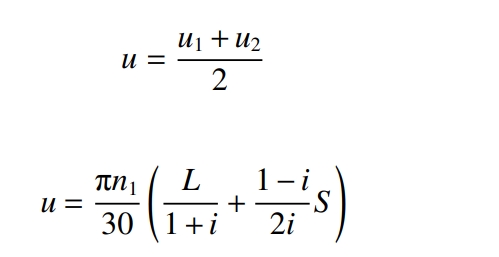
minimum oil film thicknesshmin as a function of the entrainment velocityThe increase in the suction velocity is a function of n1, L, i, and S.By differentiating equation (12) with respect to the variables L, i, and S, we obtain:
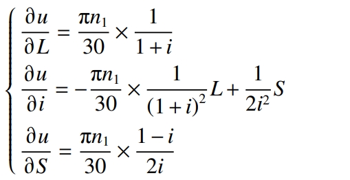
In gear transmission design,Generally, L, n1, and i are set to constant values, and u is only a function of S.At that time, u decreased with the increase of S, and at the beginning of the pinionThe entrainment velocity uB1 at the initial engagement point B1 is the smallest;when , ,At this time, u is a constant and does not change with S;when , , uIncreases with S, and the entrainment velocity uB1 is the maximum at the point of engagement B1.The entrainment velocity uB2 is the smallest at the point of engagement B2, as shown in the figure. WhenWhen n1 and i are constant values, the entrainment speed of the gear pair is along the coordinate S of the meshing linewhich showed a linear change.
Load per unit contact length
For the general involute cylindrical gear transmission, the degree of coincidenceThe range is .During a gear engagement cycle, there is a singleThe tooth pair meshing area and the double tooth pair meshing area.In the single tooth pair meshing area, the teethThe normal load FN on the face is completely borne by a pair of gear teeth,In the case of the joint area, the normal load FN is distributed to the two pairs of meshes according to a certain ruleThe teeth, which are jointly borne by them.
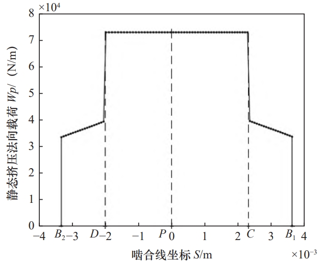
W1 = FN
FN is the total normal load on the tooth surface of the meshing gear pair;W1,W2 is the normal load borne by each of the meshing tooth pairs 1 and 2;kc1,kc2 is the time-varying meshing stiffness of the meshing tooth pairs 1 and 2 along the meshing line;qj is the load-bearing fraction of the jth meshing tooth pair when the double-tooth pair is engagedThe proportion coefficient.
Influence of gear pair geometric parameters on lubricant film
As can be seen from the formula, the minimum oil film thickness is not only related to the lubricating oilBesides its own performance parameters, it also depends on the transmission ratio i, the modification factor x,The meshing pressure angle, meshing center distance and other gear pair parameters are related.In order to analyze the influence of parameter changes on the minimum film thickness,Lubricating oil dynamic viscosity η0 = 5.41×10⁻⁸ (MPa·s), viscosity pressure coefficient α*=2.272×10⁻² MPa−1, equivalent elastic modulus of gear E′= 2.07×10⁵ MPa, and the rest parameters are selected according to the gear parameter table 1, and the minimum oil film thickness for gear lubrication is calculated.
Influence of transmission ratio on minimum oil film thickness
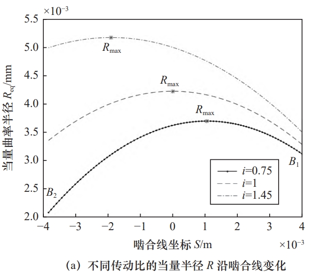
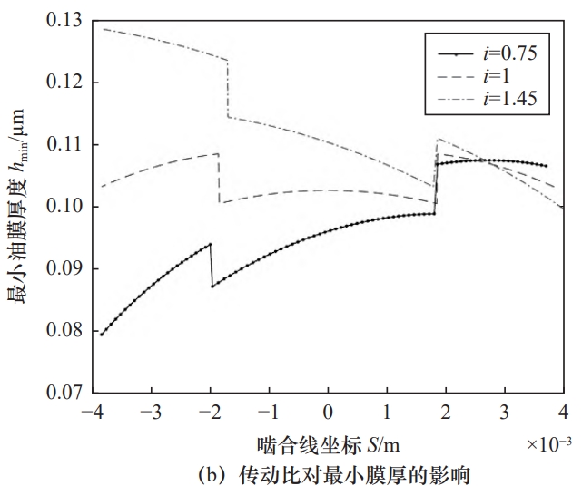
Make parameter changes to the relative gear parameter table 1, selecting the small gear teethThe numbers are z1=20, z2=15, 20, 29, and the modulus m=2. The transmission ratio is i=The minimum oil film for standard gear transmission in the following three cases: 0.75, 1, and 1.45The thickness is calculated, and the result is shown in the figure.
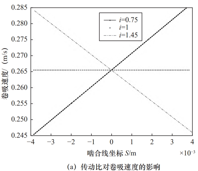
As the transmission ratio i increases, the gears are entrainedThe speed curve is the entrainment speed at the coordinate 0 point (at node P) of the meshing lineRotate clockwise about the point u0 as the axis, and the entrainment curve is downwards (i=0.75)Gradually turning upward (i=1, 1.45), the result is the same as that of the previous formula (13)The analysis is consistent;similarly, the equivalent radius R increases with the transmission ratio i,The curve gradually turns from downward (i=0.75) to upward (i=1,1.45), the instantaneous equivalent radius of curvature R at each meshing point also increases with i.and enlarged, as shown in the figure.
As the transmission ratio increases, the curve will show a meshingStarting from a certain point in the middle of B1C segment as the center point, the curve descends from the bottom(i=0.75) gradually turns upward (i=1, 1.45); generally calculatedYes, taking the oil film thickness at the meshing node as the benchmark, the gear lubrication state can be determined. The average minimum oil film thickness increases with the transmission ratio.Increased.