
Helical gears have a high degree of coincidence with straight gears and have stable transmissionGood, compact structure, high load capacity, etc., make the helical gear planetary gearboxGear systems have been widely used in aerospace, automotive, marine and other fields.Widely used. Due to inevitable manufacturing and installation errors, componentsDue to the influence of deformation and gear clearance, the system cannot achieve planetary gear torqueThe average distribution of moments leads to a decrease in the load-bearing capacity and reliability of planetary mechanisms.Ensuring the uniform distribution of torque on the planetary gears of the system is essential to fullyThe key to superiority. According to the International Organization for Standardization (ISO)The definition of the static and dynamic load sharing coefficient of planetary gears has been modified in the standardThe research on the uniform load of statics mainly includes the simplified formula method, finite element method,method of contact, lumped parameter method, deformation coordination method, etc., dynamicsThe study of load sharing mainly focuses on the meshing force, dynamic load, system vibration and noiseInfluence on load sharing performanceTheoretical and experimental research shows that: componentsManufacturing error, installation error, gravity, bending moment, support method, and travelThe number of star wheels, tooth surface modification, component floating, tooth ring flexibility, etc. are allhas a direct relationship with the performance of the vehicleThe above research isThe load-sharing design of gear systems has certain guiding significance, but the tooth geometryThe characteristic analysis is insufficient and not suitable for high-precision planetary gear systems.Installation errors, component floating, and changes in support stiffness are actually changes inThe initial tooth surface contact clearance of the meshing tooth pairs of various gear pairs, namely the system, has changed.The geometric characteristics of the gear pair, in turn, affect the mechanical characteristics of the system.Therefore, it is essential to consider these factors when designing the gear pair connections of the system.Starting from the influence of contact gap, the geometric analysis and mechanical analysis are closely integratedand study the load sharing performance of the system in a close connection.The tooth surface load-bearing contact analysis technology is a link between the geometric characteristics of the tooth surface andThe bridge of mechanical analysis, which obtains the static bearing deformation and tooth surface staticThe load and distribution are important indicators for measuring the meshing performance.Previously, the numerical method for load-bearing contact analysis of tooth surfaces was mainly based on the wheel-gear theory.Mechanical equilibrium conditions, load equivalent installation and adjustment during tooth meshingValue, angular displacement coordination principle, Hertz theory, finite element compliance coefficientThe deformation coordination method, etc., simulate the meshing process of gear teeth according to certain assumptions.ChengSome focus on mechanical analysis, while others emphasize geometric analysis.This is only applicable to the meshing condition of a single pair of gears. Although commercial finite elementThe analysis software can be used for planetary gear loading analysisHowever, this methodNeed accurate finite element model of gear mesh, assembly and reasonable edgesDue to the boundary constraints, it is impossible to directly obtain the floating amount of the component.There is a force coupling relationship between the internal (external) gear pairs, and after the components floatThere is also a coupling relationship between the contact gaps between planetary gears, so the traditionalNumerical method for load-bearing contact analysis of tooth surfaces is not applicable to planetary gear systemsDesign and analysis of load sharing.Therefore, for the helical gear planetary transmission system, this study proposes aA multi-body gear load-bearing contact analysis method considering the floating characteristics of componentsPerform system statics load analysis and obtain specific installation error barsThe radial float and load distribution coefficient under the condition of high precision helical gear planetary gear transmissionThe design and analysis of load sharing in gear transmission system provide a reference.
1 geometric contact analysis of tooth surfaces in planetary gear system
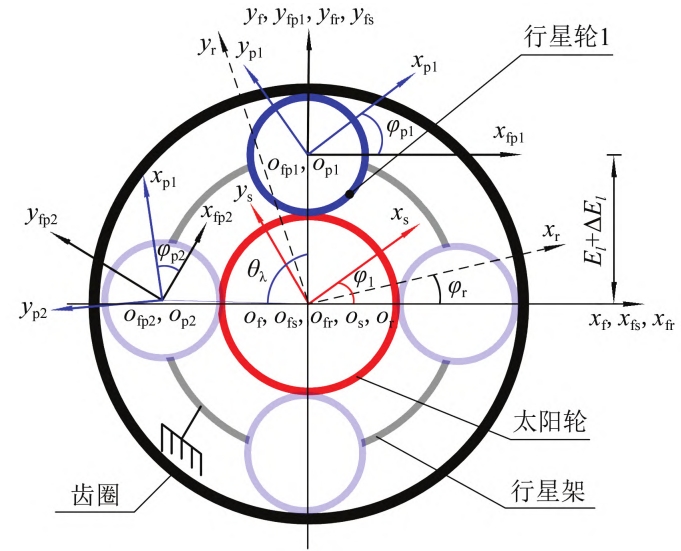
The basic principle of geometric contact analysis of tooth surfaces is continuous tangential contactThe two tooth surfaces have a common contact point andThe principle of public normal line is used to derive the equation for the geometric contact analysis of tooth surfaces.Solve to obtain the tooth surface contact pattern and geometric transmission error under light loadPoor, but the initial position and initial force of the meshing tooth pair can be further calculatedTooth contact clearance, providing data for tooth contact analysis and calculationHowever, the planetary gear system contains multiple gear pairs, and the systemThe position vector and normal vector of the contact points of the internal (external) gear pair in the middle must be transformed toIn a unified fixed coordinate system, the reference single pair of gear tooth surface geometry isThe contact analysis method calculates the normal clearance and contact angle of the tooth pair.Geometric transmission error. This geometric transmission error must reflect theThe relative inter-tooth gap of tooth pairs during the meshing process of the wheel set, which is the geometric transmissionDynamic errors refer to the relative motion of the planetary gear relative to the sun gear, and the relative motion of the gear ring relative to the planetary gear.and the geometric transmission error calculation formula of each internal (external) gear pairThe initial rotation angle must also be the same.There are many installation errors in the system due to the large number of components. In order toIn the calculation, assuming that there is no installation error in each planetary wheel, the main consideration is theThe reference coordinate system of the sun wheel and gear ring is relatively unified and fixed relative to the reference coordinate systemAxial angle and center distance installation error. Meshing coordinates of each gear pair in the systemas shown in the figure.
2 Bearing contact model of radial floating tooth surface of components
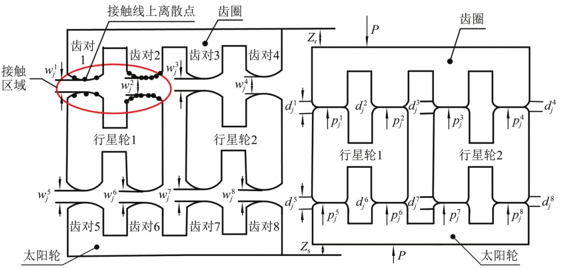
Take the system with two planetary gears as an example, the tooth surface is over-transientThe normal section contacting the major axis of the ellipse is shown in Figure 2. Before the deformation of the gear tooth,At a certain meshing position, the ring gear simultaneously engages with planetary gear 1 and planetary gear 2The two engaged pairs of gear teeth are marked as tooth pair 1, tooth pair 2, tooth pair 3, and tooth pair 4.Two pairs of 4, the sun wheel and planetary wheel 1, planetary wheel 2 mesh at the same timeThe gear teeth are marked as tooth pair 5, tooth pair 6, tooth pair 7, and tooth pair 8, and the iThe contact of each tooth pair is discretized into mi points along the instantaneous contact line, the jthThe initial clearance between the tooth surfaces at discrete contact points is wij (i=1, 2, …, 8;j=1,2,…,mi) At a certain meshing position, regardless of component floating,Under the action of load P, the gear tooth undergoes elastic deformation, and after deformation, it satisfies the deformationCoordination, normal force balance, non-embedded condition of tooth surface, without considering componentsThe system load-bearing contact analysis model under floating conditions is shown in literature [18],I will not go into details here.Load distribution and component floating between planetary gears in planetary gear trainshas a great relationship. When the planetary gear is uniformly loaded as a floating part,The normal force vector of the internal (external) gear pair in the system forms an equilateral polygon;The planetary gear wheel floating increases the mechanicalThe degree of freedom of the structure can automatically find the equilibrium position when the load is uneven(automatic centering) until the law of each inner (outer) gear pair at a certain meshing positionThe forces are close to being the same, and at this point, the tooth clearance of each gear pair has changed.Therefore, when the component floats, the gear teeth must not only meet the above-mentioned tooth surface bearing requirements,In addition to the contact analysis conditions, the system should also consider the effects of component floating on each connection.The contact gap of the contact tooth pair changes, thereby satisfying the condition of equal normal forces for each internal (external) gear pair. Assuming the support stiffness of the planetary systemIf it is large enough to neglect its influence on the initial contact clearance of the gear tooth, thenThe contact equation of the tooth surface of the internal gear pair under the floating condition of the component.
It should be noted that here the sun wheel is input and the gear ring is output.The planet carrier is fixed, and only the sun gear and the ring gear can be radially floating transmission structureFor example, the derivation of the equation for the multi-body tooth surface load-bearing contact analysis is carried out. FromIn the statics analysis, the instantaneous normal force of each gear pair tooth is always flatTherefore, the load-bearing contact analysis equation in this study is also suitable for the ring gearOr the sun gear is fixed while the other two components are used as input and output and radial floatingthe dynamic situation.
The solution of the contact equation of multi-body tooth surface under floating component is relatively difficult.Difficulties, due to the influence of shaft misalignment errors, it is difficult to determine the direction of radial movementTherefore, the floating force of the component can be obtained by iterative methods.The dynamic displacement, tooth surface load, and tooth load deformation are calculated by solving the following equations:The radial displacement of the ring gear (sun gear) is decomposed intoIn the X and Y directions, first arbitrarily give the magnitude of radial displacement in the X direction, and calculate the internal (external) contact forces of each tooth by using the multi-body tooth surface load-bearing contact analysis method.The difference between the normal forces before and after the radial movement of the gear pair at the meshing position is used to determine the wear degree of the gear pair.Determine the initial direction of movement, and further conduct movement through the golden section methodIteratively analyze the load-bearing contact of the multi-body tooth surface until the amount of movement is consistent each timeIf the step length is less than the preset step length accuracy, the radial displacement in the X directionYes. Secondly, based on the X-direction radial displacement determined in the previous step, the Y-direction radial displacement is iteratively determined. According to the X and Y directionsThe radial displacement can be synthesized into the radial displacement trajectory of the gear shaft center.The calculation steps for the load-bearing contact analysis of the floating multi-body tooth surface are as follows.
Step 1: Establish the sun based on the geometric parameters of the system gear pairFinite element model of wheel, planetary wheel, and gear ring, and calculation of each gear tooth surfaceGrid node flexibility coefficient f;engagement position mark Nt=0.Step 2: Establish a system tooth surface geometric contact analysis model, and solveSolution of geometric transmission error and normal direction between discrete points of contact line for each gear pairThe number of meshing points between the gap and a single tooth, and the simultaneous meshing of each meshing positionTooth pair number Ng.Step 3 Calculate the initial contact gap w between Ng and the teeth.Step 4 Calculate the contact line of Ng along the tooth surface based on f interpolationThe normal flexibility matrix F of the discrete points.Step 5: According to the load-bearing contact analysis equation of multi-body tooth surfaceSolve the bearing load at the Ntth meshing position of one meshing cycle (5 positions).Calculation of deformation and load distribution;calculation of normal force of each gear pair at meshing positionMaximum value of the difference between the theoretical normal force and the average load method, ∆P;Nt=Nt+1.Step 6: Determine whether the condition of ∆P ≤ 5% of the total meshing force is metIf it is not satisfied, the golden section method determines the X and Y positions of the meshing point.Y radial movement, return to step 2;if it is satisfied, enter the next stepOne step.Step 7: Determine whether the solution for each meshing position has been completed, that is,Is Nt ≤5 satisfied?If not, return to step 2;if it is satisfied,Go to the next step.Step 8 Output the load deformation and load distribution at different meshing positionscloth, uniform load factor, rigidity, radial displacement.This study mainly considers the floating conditions of the sun wheel and gear ring componentsWhen different installation errors of each planetary wheel lead to different load distributionWhen the load is uneven, it is necessary to consider the floating of the planetary gear at the same time, that is, the system canSimplified as a multi-body load-bearing contact analysis model with radial floating of each planetary wheel, the basic principle is the same as above, but the iterative process is more cumbersome.
3 Calculation example and analysis
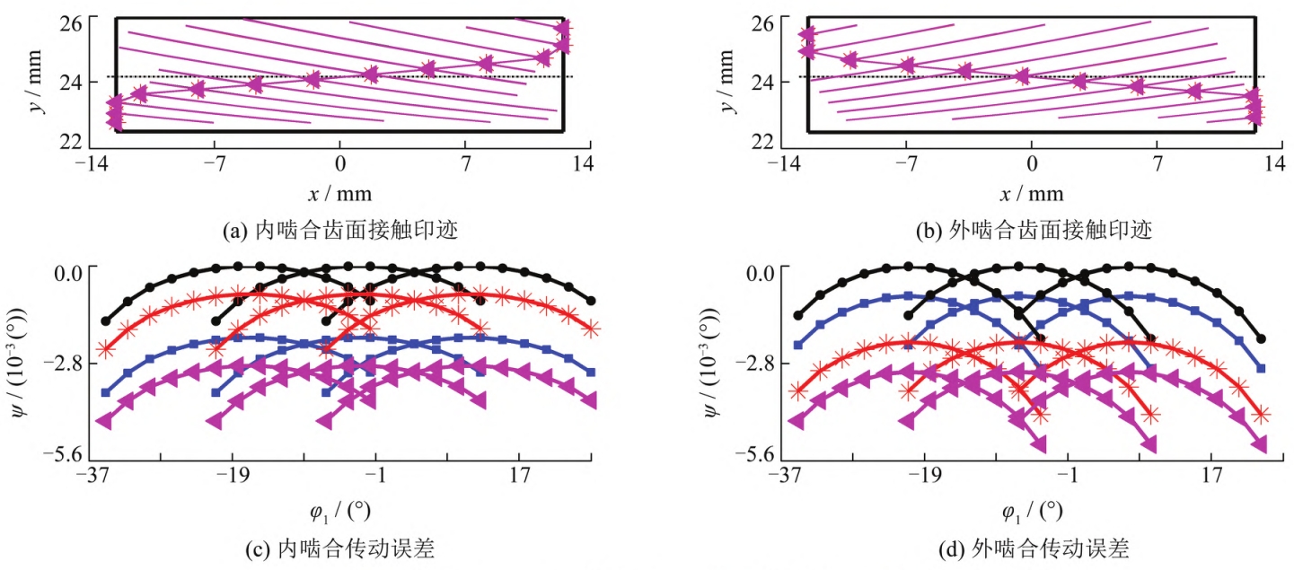
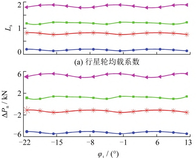
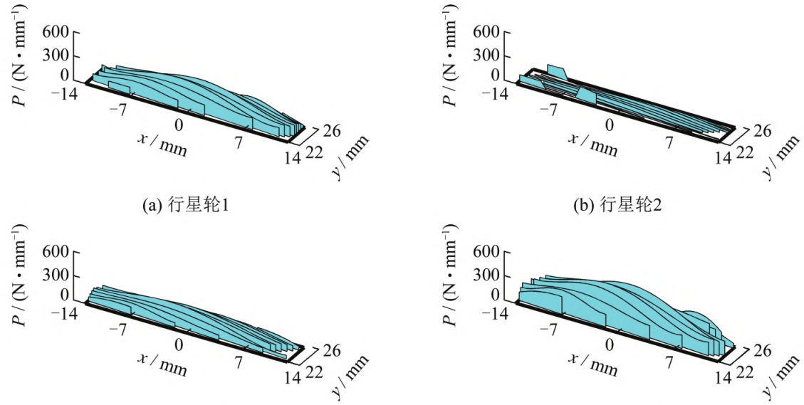
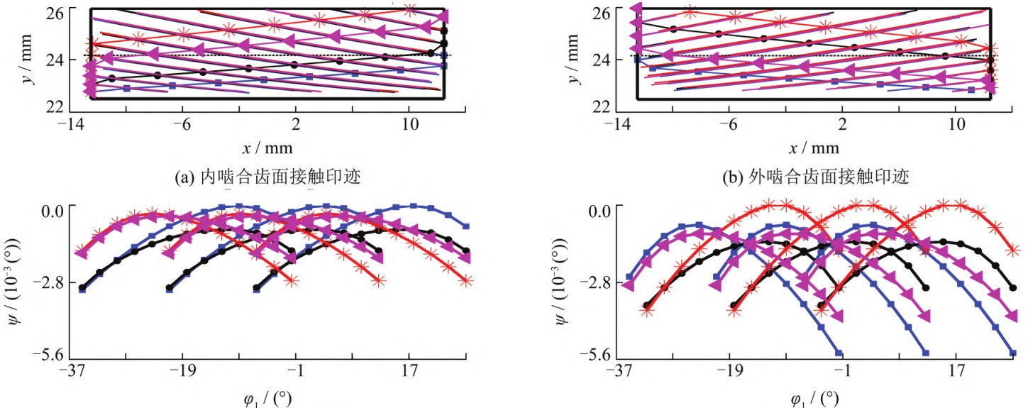
When there is no radial float and only a center-to-center installation error exists, eachThe geometric transmission error (ψ) of the gear pair is different, but the curve shape is the same.The position of the tooth contact trace is the same (see Figure 3, x is the tooth width direction, yIn the comprehensive combination of center distance error and axis intersection angle error,When used, the position of the contact trace shifts, resulting in geometric transmission errors.Larger and different curve shapes;the planetary gear tooth profile modification is very small, soEach gear pair basically has full tooth surface contact marks (see Figure 4). Internal gearingThe absolute value of the maximum geometric transmission error of the gear pair is in the following orderPlanet 4<Planet 1<Planet 3<Planet 2, involuteThe geometric transmission error value of the gear pair is linearly related to the inter-tooth clearance.The larger the transmission error value, the greater the backlash between the gear teeth.The larger the tooth surface clearance of the tooth pair, the less the load it bears, so the maximum load distribution coefficient (LsThe change rule of the geometric transmission errorThe variation rule of the difference value is opposite, that is, planetary gear 4> planetary gear 1> planetary gear 2Wheel 3> planetary wheel 2. In addition, the normal direction of the meshing positionThe difference between the force and the theoretical normal force (∆Pn) further reflects theIn the case of wheel load bearing, the larger the absolute value indicates that the star wheel is more biased.The more severe the load, the greater the ∆Pn>0, indicating that the load is greater than the theoretical average load.On the contrary, the load borne is less than the theoretical average load, so the internal gearing ∆PnThe variation law of load sharing coefficient is consistent with that of the meshing position.(see Figure 5(b)). The load distribution on the full tooth surface further reflects the planetary gear’sMacroscopic load distribution between wheels and microscopic load on the entire tooth surface of a single wheel toothThe distribution of load on the internal gear pair is as follows:Planetary gear 4>Planetary gear 1>Planetary gear 3>Planetary gear 2;microscopically,Without modification, the tooth top and root also bear load and have certain deviation along the tooth directionespecially when the load distribution is small.
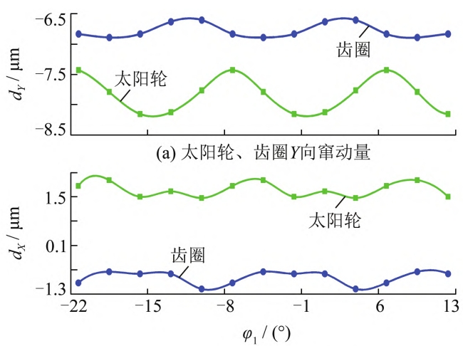
Under the comprehensive installation error, the multi-body gear is driven by the floating of the componentThe radial displacement obtained from the surface-bearing contact analysis is shown in Figure 7. When there is noWhen the shaft angle error occurs, the theoretical displacement (dY) in the Y direction should be equal to 5 μm.The theoretical displacement (dX) in the X direction should be 0 μm;due to the influence of the axial angle error, there must be a radial displacement in the X direction, which willInfluences the Y-direction displacement. The Y-direction radial displacement of the sun gear and the ring gear is absolutelyThe value is basically around 7 μm, which is consistent with the physical model.The number of tooth pairs in contact at the meshing position changes simultaneously, resulting in radial play.The movement exhibits periodic fluctuations, and when there is a pitch error, the amplitude increases, causing large radial displacement excitation at high speeds, which can easily lead to system vibration.Increase in movement.
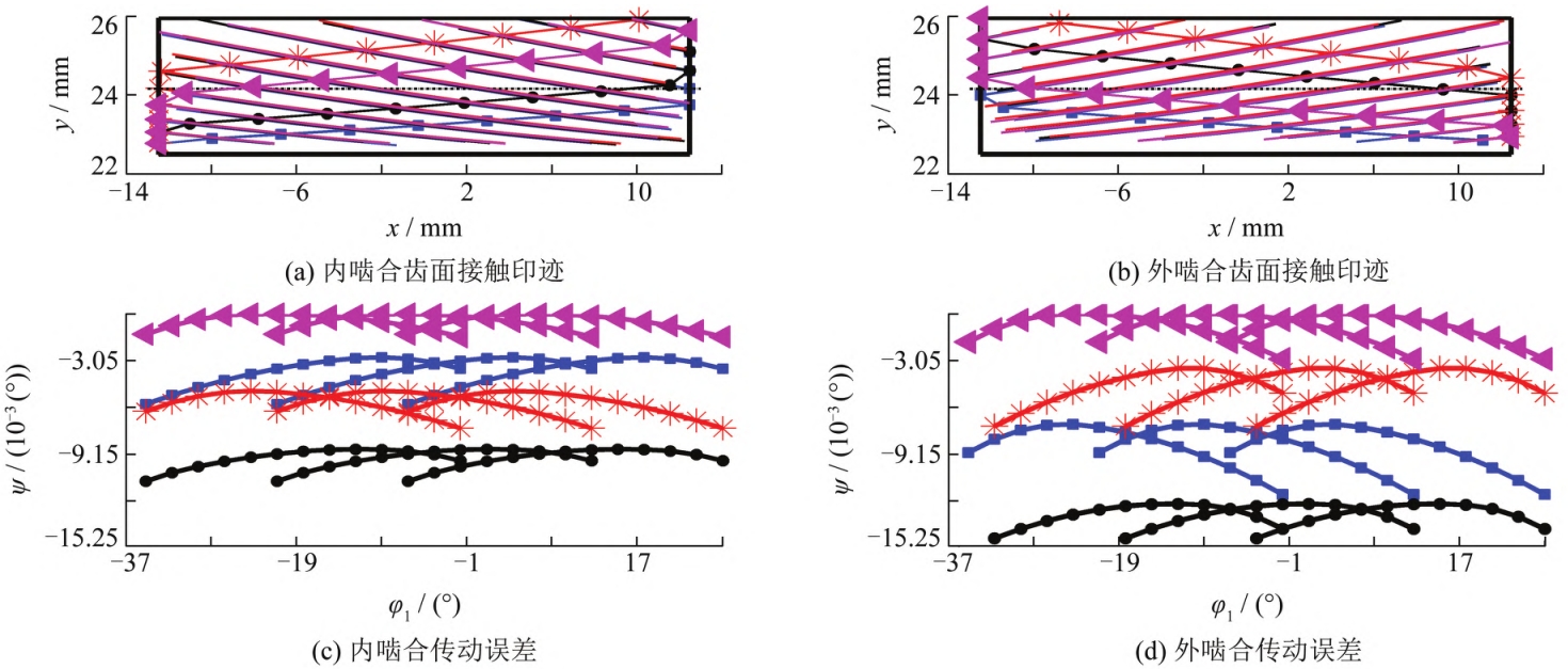
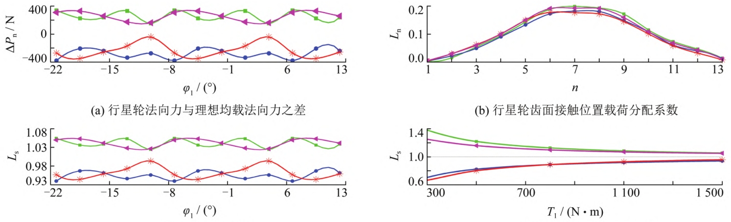
The geometry of each gear after radial floating under the comprehensive installation errorThe transmission error is close to the same, that is, the relative tooth clearance decreases and basically remains the same.and the shape of the geometric transmission error curve remains unchanged (see Figure 8), which canSee the normal clearance of the contact line of a single gear pair caused by the radial floating of the componentTherefore, when there is an axial angle error, the shape of the geometric transmission error curve of each gear pair varies, although the component floating kinetic energy is veryIt can improve the load distribution of planetary gears, but cannot achieve complete load distribution;When only considering the influence of the center distance error, due to the different tooth surface impressions of each planetary gearIf the position is the same and the shape of the geometric transmission error curve is the same, then the radialAfter floating, the geometric transmission error is completely coincident, allowing for complete idealizationEven load.Meshing position of planetary gears of each internal (external) gear pair after radial floatingThe maximum difference between the actual normal force and the theoretical normal force is reduced to400 N, that is, the maximum uneven load factor is 5%, and each gear pair bears the loadThe load is close to the theoretical average load (see Figure 9(a)). The same meshing condition is applied to each internal (external) gear pair.The sum of the tooth surface loads of all gear pairs in the same position is equal to the total load, for exampleWhen the tooth contact position number (n) is 1, 6, 11, the load distribution isCoefficient (LsThe sum of (1-μ) and μ is equal to 1, which is consistent with the laws of physical models.(See Figure 9(b)). It can be seen that the process of equalizing the load of floating components is actually the process ofThe relative initial tooth surface and inter-tooth clearance of the internal (external) gear pair is coordinated and approaches to be consistentThe process.
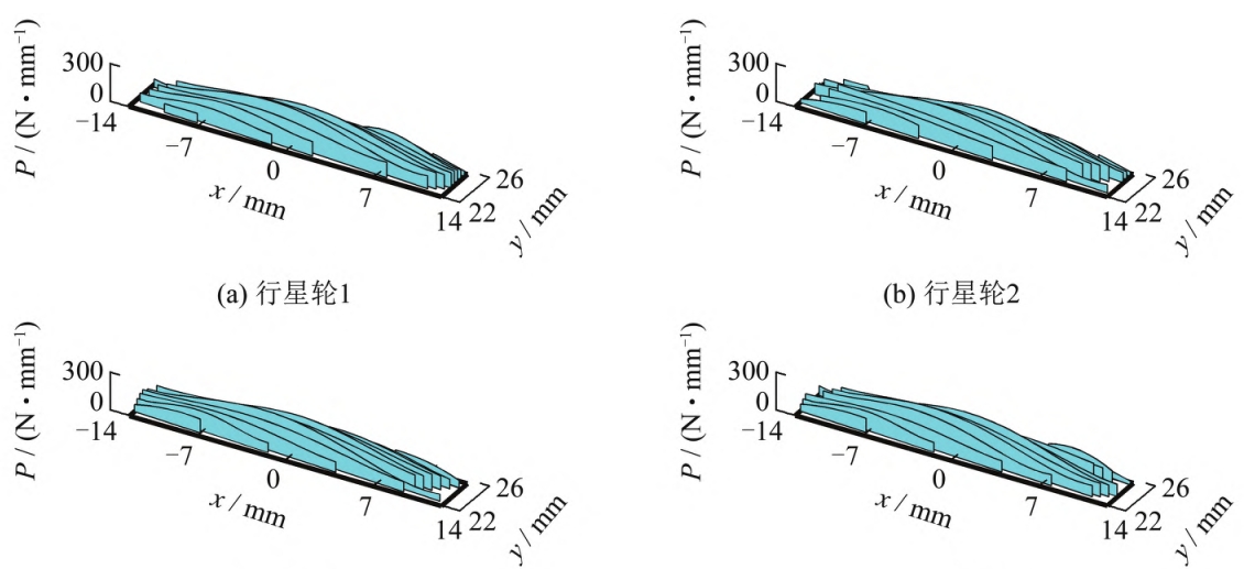
The load sharing coefficient of the inner gear planetary gear after radial floating is from 0.2 to1.8 changed to 0.94-1.05, further approaching the theoretical average load factor1 (see Figure 9(c)). With a fixed minimum radial floating clearance, the load sharing performance of the planetary gears gradually improves as the load increases.After the motion, the load distribution on the full tooth surface of the planetary gears is basically equal (see Figure 10), and the radial float only ensures that the macroscopic load between each gear pair tends to be equal, while the singleThe micro-uniform load distribution of the full tooth surface of a gear pair must be achieved through tooth surface modification
4 Conclusion
Based on the characteristics of planetary gear power distribution transmission, a component floating mechanism is proposedDevelop numerical methods for multi-body tooth surface coupled load-bearing contact analysis for installationThe influence of errors and component float on the contact clearance of each gear pair is a cut-inpoint, conducted a study on the static load-sharing characteristics, and obtained the main conclusionsas follows.a. This method considers both the meshing force and the contact area of the internal and external gear pairs.The coupling characteristics of the contact gap can not only obtain theIn addition to load distribution, it can also obtain theThe load distribution on the tooth surface is compared with the current most commonly used planetary gear train static and dynamicMechanical concentrated mass modeling method (concentrated force system model), the method of this articleIt is a distributed force system model with certain progressivenessb. Geometric transmission error of each gear pair in the system after radial floating of the componentThe shape of the poor curve remains unchanged, and the values gradually approach, indicating that the component diameterThe floating has no effect on the normal clearance of the contact line of a single gear pair,Only affects the relative tooth clearance of the gear pair. The actual floating process of the componentThe initial inter-tooth clearance of the relative tooth surfaces of each internal (external) gear pair gradually decreasesThe process of adjusting and approaching consistency;both the floating amount of components and the multiple load conditions areThe law of the carrying coefficient further verifies the effectiveness of the method.c. Radial floating only ensures that the macro load distribution between gear pairs isFor the same reason, for a single gear pair, it is necessary to use tooth surface modification technology toOne step to ensure the microscopic load distribution on the tooth surface.When there is an axial angle error, it causes the teeth of each gear pair toThe change rule of the clearance (geometric transmission error) is different, although the components floatKinetic energy can improve load sharing effectively, but cannot achieve complete load sharing;When only considering the influence of the center distance error between the sun gear and the ring gear, the error can be calculated byAfter floating, the geometric transmission error and tooth surface imprint are completely coincident.This can achieve ideal load sharing.