
External gear pump is the most widely used aviation oil pump, due to itsIt has simple structure, good maintainability, mature technology, small size and light weight.In the fuel and lubricating oil system, it is generally used as a booster pump and oil supply pump, with high pressure and high temperature resistance.The ability to optimize the performance of mechanical hydraulic systems is crucial. The performance and structure of gear pumpsThe structure parameters are closely related, while the internal flow of the gear pump can be more directly observedreflecting the influence of structure on performance. Sudden changes in oil pressure in the trapped oil zone,Gear pump components are subjected to high impact loads, which can greatly affect their working life.Both the life and stability are affected. At the same time, there is a large internal leakage and a large radial force.It is also the biggest disadvantage of gear pumps. Therefore, gear pump design shouldThe influence of the internal structure of the pump on the flow should be considered in order to meet high-standard designAt present, numerical simulation of the internal flow field of gear pumps is the most effective way to study the gear pumpimportant means for optimizing the internal structure of pumps.Due to the complexity of the internal gear movement and working medium flow in the gear pump,The numerical simulation of sex is relatively complex, and research has been carried out at home and abroad.determining research work.A method for calculating the double integral using Green’s formula is proposed to calculate the interface area of the external gear pump, and thevalidated in the computer-aided design model. With the help of Fluent software,The dynamic grid technology of CFD was applied to analyze the internal flow field of a certain type of gear pump.Study the internal leakage and trapping of gear pumps under different speeds and load conditionsOil and flow pulsation output status. Using Fluent software systemThe fluid dynamics characteristics of the internal flow field of the gear pump are analyzed systematically, and the internalThe pressure distribution cloud image of flow provides a new method for the structural optimization of gear pumps.Method. Using Fluent software to study the dynamic characteristics of an external gear pump inThe influence of different side clearance on trapped oil pressure, and the effect of gear speed on trapped oil pressureThe internal velocity flow field distribution of the wheel pump, obtaining the influence of clearance and rotational speed on volumetric efficiencyThe impact of the rate.The internal dynamic simulation of gear pumps helps to reflect the flow inside the pump realisticallyTo investigate the changes of the structure, the author used the ANSYS finite element analysis software to analyze the modelPre-processing module, fluid calculation and analysis module, post-processing module, combined with twoThe dynamic grid technology is used to simulate the rotation of a certain type of aviation external gear pump.dynamic flow in the process. According to the known boundary conditions and geometric parameters of the gear pump,The number is simulated and solved using Fluent software dynamic grid technology, and theThe distribution of the dynamic flow field inside the gear pump is obtained, and the visualization results are presented.Research the relevant parameters in the dynamic flow field of gear pumps, such as pressure, speedThe distribution and change of the gears, in order to optimize the structure of the gear pump and develop new types of gears.The design of the wheel pump provides a reference.
Fluid dynamics of gear pump
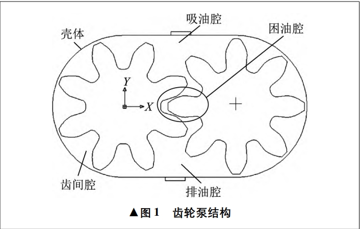
Fluids follow the conservation of mass, energy, and momentum during their motion, as well asIn the process of motion, it is also necessary to consider the composition of the fluid and turbulence.The gear pump has a simple structure and achieves fluid transmission through the meshing of gears.The structure of the gear pump is shown in Figure 1. The fluid state caused by the gear pumpIt is more complex, so the governing equation should be introduced for mathematical description.
Basic control equations of fluid dynamics
(3) Energy conservation equation. The energy conservation equation is the first law of thermodynamics.The expression of the law in fluid mechanics is a flow system involving heat exchange.The basic law that must be satisfied by the number, that is, the increase rate of energy in the infinitesimal element is equal toThe net heat flow and body force of the micro-unit entering the micro-unitAchievement.
The turbulence phenomenon of fluid flow is ubiquitous in nature, due toThe irregularity of turbulent motion makes it difficult to deal with turbulence problems.Generally speaking, there are two types of treatment methods. One is through experimentationAnother method is to use numerical simulation. Turbulence numberValue simulation is divided into direct numerical simulation and indirect numerical simulation, which can beIt is summarized in the form of a distributed flowchart.
The most widely used turbulence model in the simulation of fluid machinery isStandard k-ε model, and renormalization developed from the two-equation modelThe k-ε model, the realizable k-ε model, the shear pressure transmission k-ε model,Among them, the standard k-ε model and the renormalization group k-ε modelType is more commonly used.
1) Standard k-ε model. The standard k-ε model is based on the turbulent flowA semi-empirical formula consisting of k and diffusivity ε. For turbulent kinetic energy k,have
(2) Renormalization group k – ε Model. This model considers the fluidThe problem of rotation has been improved in the term of diffusivity ε, making the calculationThe accuracy of the method is improved, which greatly compensates for the standard k-ε model.
The flow field distribution inside the gear pump is very complex, and during the fluid flow process,There will be rotation and fluctuation, especially in areas with relatively narrow gaps, which willThere is a great vibration, such as at the gear meshing and tooth tip clearance.Compared with other turbulence models, the renormalization group k-ε model is used for calculation and solutionComplex vortex and rotation are more adaptable and can better handle high strainRates and streamlines with large bends are avoided in the standard k-ε model in strong rotationDistortion produced by flow, curved wall flow, or curved streamline flow.
For problems where the computational boundary undergoes motion or deformation, FluentThe software uses dynamic grid to perform computational simulation. Fluent dynamic gridThere are three methods provided, namely, layering method, fairing method, and reconstruction method.The dynamic grid model can be used to simulate the change of flow field shape due to boundary motion.The problem of time change. The form of boundary movement can be predefinedMotion, which can be specified before calculation in terms of speed or angular velocity, orThe motion that is not defined in advance, that is, the motion of the boundary, should be calculated by the previous step.The result is determined by calculation.
The update process of the grid is implemented by Fluent software according to the optimization results of each iteration step.The change of boundary is automatically completed. When using a dynamic grid model, it is necessary toFirstly, the initial grid and the boundary movement method must be defined, and the participatingMoving area. It can be determined by using a boundary function or a user-defined function.The motion mode of the boundary. Fluent software requires that the description of motion beThe meaning is on the grid surface or grid area. If the flow field contains bothTo move two regions, they need to be combined in the initial grid,identify them. For those that occur due to motion in the surrounding areaThe deformed areas must be combined into their respective initial grid areas.The grid between different regions does not have to be regular, and non-regular or sliding interface functions provided by Fluent software can be used in model settings toConnect the area.
Taking a certain type of aviation external gear pump as an example, the main parameters of the gear pump areThe number of teeth is 8, the module is 3.5 mm, the pressure angle is 20°, and the center distance is42 mm, rated working pressure of 5.5 MPa, rated speed of 5000r/min。
Generate involute gears in AutoCAD drawing software and set the teethThe two-dimensional model of the gear pump is established based on the wheel center, pitch circle, and number of teeth.
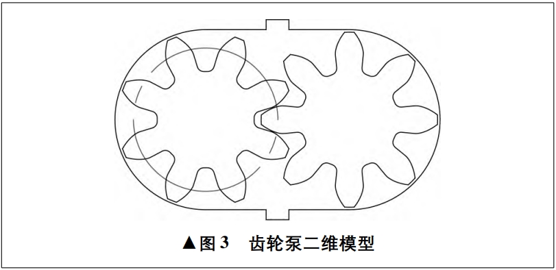

Note that in Gambit software, only coordinate parameters can be used forTherefore, when creating in AutoCAD software, it is important to selectCoordinates, such as taking the center of the circle as the origin of coordinates.Due to the irregular shape structure and complex internal flow field of the gear pump,At the same time, considering that the grid of the calculation area will undergo significant deformation during the calculation,Therefore, triangular grids are used for regional division.
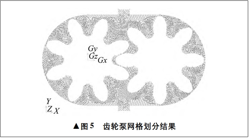
Click the Operation option on the command panel on the right side of the Gambit software window.in the Mesh button, click the Face button, and then click the MeshFaces button, hold down the Shift key to select the model, and click the corresponding dialog boxIn the , set the Elements to Tri and the Type to Pave, Interval SizeSet it to 0.2, and other values are default. Click Apply at the bottom of the dialog boxThe button is clicked, and the entire grid division is completed. The resulting final gear pump grid divisionThe results are shown in the figure.
Click the Zones button in the command panel, and then click SpecifyClick the Boundary Types button to set the boundary conditions in the pop-up panel.The top line segment is set as the pressure inlet boundary, named Oilin, and theThe following line segment is set as the pressure outlet boundary and named Oilout, as followsIt is equivalent to setting the gear pump to rotate counterclockwise on the left gear, with the lower gear rotating clockwise.The upper part of the oil port is the oil suction port.
Theoretical analysis shows that the inlet and outlet of the gear pump have a significant impact on the flow rate of the gear pump.There is no impact. The author analyzes the influence of the size of the inlet and outlet on the pressure field andThe influence of the speed field, so that appropriate access can be designed during designThe inlet width is increased to 6.5 mm, which is calculated by Fluent softwareThe resulting pressure and velocity cloud maps are shown in the figure, and the pressure and velocity distributions are as followsas shown in Figure .
During the above simulation process, the pressure difference between the front and rear of the gear pump is generated by the rotation of the gear pump.The cause is self-priming, while in practical use, there are valves with equal pressure difference and overflow valves.The door should maintain a certain pressure difference between the front and rear of the gear pump.When entering the meshing gear pair, the nearby volume decreasesWhen the pressure increases, the disengaged gear increases the volume nearby, and the pressureAlthough the time pressure may vary at different times, it still follows theThe law of.As the radial clearance of the gear pump decreases, theThe body pressure increases significantly, but the pressure distribution law inside the pump remains unchanged. At the same time,Compared with the graph, the pressure on the inlet section appears to be small in the middle and large at both endsThe general trend is that the speed tends to be large in the middle and small at both ends, which is caused by the rotation of the gears sucking in oil.
The size of the inlet and outlet of the gear pumpIt affects the pressure field and velocity field of the gear pump. The increase in inlet and outlet port sizes reduces the pressure and velocity inside the pump. The increase in inlet and outlet port sizes also reduces the inlet pressure andThe speed has significantly decreased, but the pressure and speed of the middle part of the inlet are relatively higher than those of the two ends.The change is small, so the increase in import and export also has an impact on the flow of the gear pump.The pulse of flow is reduced, which is consistent with theoretical calculations.The pressure field distribution in the gear pump under constant pressure is given byThe pressure distribution law of pressure increasing gradually from inlet to outlet, compared with non-constant pressureSimple. The speed is also significantly higher than that under non-constant pressure conditions, which is due to the constant pressureThe inlet and outlet pressures of the gear pump under the constant pressure state are higher than those under the non-constant pressure state.The pressure of the mouth.
Distribution of velocity field and pressure field at different times and under different parametersIt can be seen that the low pressure zone, low speed zone and discharge chamber of the gear pump’s inlet chamberThe high-pressure zone and high-speed zone are alternately distributed between the two gears, which are in meshing state with the gearsrelevant, but also at different times, the gears will experience different impact forces,which will affect the service life of the gear pump.
Based on the research of dynamic grid technology, the application of Fluent softwareSimulation analysis of the internal flow field changes of an external gear pump under rotation conditionsThe situation is changing.
1) The maximum static pressure in the internal flow field of the external gear pump occurs at the teethThe meshing of the gears will generate large radial forces in the trapped oil area, which will causeThe upper impact gear pump life.(2) The size of the inlet and outlet of the gear pump will affect the inlet and outlet pressure andThe flow rate, but the impact on the flow rate is small, which is consistent with the theoretical analysis results.(3) The smaller the radial clearance, the lower the oil pressure and flow rate in the gear pumpThe larger the gear pump, the higher the internal pressure and the higher the requirements for gear materials. In addition, engineering experience shows that radial clearance leakage is the main factor affecting the volumetric efficiency of gear pumps.One of the reasons for the drop is that radial space should be comprehensively considered in the design process.The value of the gap.(4) Based on the two-dimensional flow field, further research on gear pumps can be conducted.three-dimensional dynamic flow field, and more accurately analyze theInternal flow field, understand the influence of gaps in the pump on gear flow, and furtherProvide assistance in designing new gear pumps and new floating bushings.