
In recent years, visual measurement has been widely applied due to its high speed, non-contact and other characteristicsIntelligent measurement fields such as visual positioning, spacing measurement, and size measurement, including packageMeasure the three-dimensional profile of the gear. At present, gear 3D profile measurement is usually carried out usingImplementing 3D point cloud data extraction and model reconstruction of gears using binocular vision technologyHowever, the initial point cloud of gears obtained by this method often has high outlier noise and redundancyHigh performance can easily lead to poor 3D reconstruction quality and low dimensional measurement accuracy of gears, which in turn affects the quality inspection and manufacturing accuracy of gears. Therefore, there is an urgent need to study the extraction and reconstruction measurement of 3D point cloud data based on visual measurementMethod to improve the three-dimensional reconstruction measurement accuracy of gears.
In response to the current research status and existing problems mentioned above, this article first utilizes the dualVisual measurement system obtains three-dimensional profile information of spur gears and analyzes itAnd using direct filtering and voxel grid filtering to remove outliers in the initial point cloudReduce data processing by removing noise and redundant points. Then use the mobile mostSmall Two Multiplication Smoothing and Greedy Triangulation Reconstruction Algorithm for Solving Surface Coarseness after ReconstructionThe problem of roughness and low accuracy. Finally, build a binocular vision gear measurement systemVerify the platform, use the extracted gear 3D point cloud data for 3D model reconstruction, and analyze the gear reconstruction effect and size measurement accuracy.
Acquisition and analysis of three-dimensional point cloud data for gears
The structural principle of the binocular stereo vision measurement system is shown in Figure (a), which isObtained the three-dimensional contour point cloud information of the gear, and used the left and right cameras to capture it separatelyCalculate the three-dimensional coordinates of the point based on the disparity between the left and right images of the target image. doubleThe experimental platform for visual measurement system is shown in Figure (b), and its equipment mainly includes2 sets of black and white industrial cameras, industrial lenses with a focal length of 16mm, and adjustable digital camerasOptical scanning head, tripod, gear, rotary table, and computer, etc.
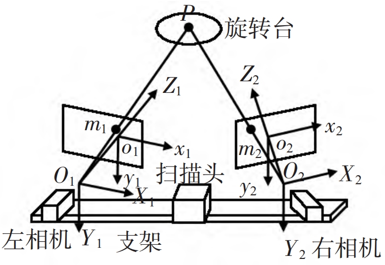
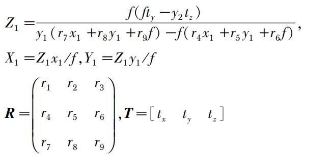
In Figure 1, the two cameras and scanning head are placed horizontally, with O1-X1Y1Z1 andO2-X2Y2Z2 represents the left and right camera coordinate systems, respectively, and o1-x1y1 and o2 x2y2 are dividedDo not use the left and right image coordinate systems, where the origin O1 and O2 represent the light of two cameras, respectivelyHeart, O1Z1 and O2Z2 are the optical axes of the two cameras. Assuming that any point P on the surface of the gear is connected to O1 and O2 respectively, point P is located on the planes o1x1y1 and o2x2y2The coordinates of the projection points are m1 (x1, y1) and m2 (x2, y2) respectively, and the left camera is positionedIf the standard system is considered as the world coordinate system, the right camera can be approximated as a monocular camera modelThe rotation matrix R and translation matrix T of the camera can be obtained through camera calibration. By combining the projection transformation formula, the three-dimensional position of point P in the world coordinate system can be obtainedThe labels (X1, Y1, Z1) are shown in equation (1)
Analysis of the Characteristics of Gear 3D Point Cloud
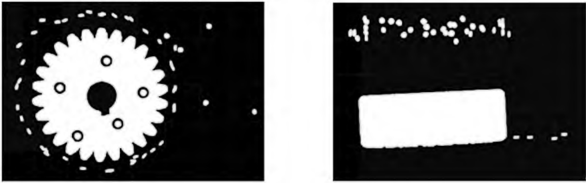
The initial point cloud data of gears obtained using a binocular vision measurement system is as followsFigure, point cloud number 2974257, and there are many outliers and redundancy in the figureRemaining points.
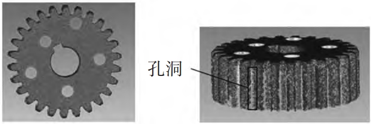
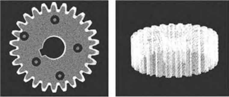
The initial point cloud data of the gear mentioned above is utilized using GeomagicControl softwareThe 3D model of the gear directly reconstructed is shown in the figure, and it can be seen from the figure that after reconstructionThe surface of the gear is uneven and there are many holes.
The analysis of the initial 3D point cloud data reconstruction results of the gear indicates that when using a binocular vision system for dimensional 3D model reconstruction, the gear needs to be removedOutlier noise in initial 3D point cloud data while preserving surface informationRemove redundant point clouds to ensure a smoother surface and fewer holes after reconstruction, in order to improve the measurement accuracy of gear size reconstruction.
To improve the surface quality of 3D point cloud reconstruction of gears, this article adopts a straight line methodRemove outliers and redundancy in the initial point cloud of gears through pass filtering and voxel filteringDot wait for noise. Among them, the direct filtering removes nonRemove outliers and noise by selecting points within the range of values. Voxel grid filteringAfter obtaining point cloud coordinatesCalculate the maximum values xmax, ymax, zmax, and minimum values xmin, ymin, zmin on the X, Y, and Z axes. Given the side length v, then X, Y, Z sitThe standard axis can be divided equally into L, M, N parts, L=(xmax xmin)/v, M=(ymax -)Ymin/v, N=(zmax zmin)/v.
In order to further improve the accuracy and effectiveness of gear 3D model reconstruction, this paper adopts the moving least squares method for point cloud data smoothing. Establish a planThe composite function f (x) is shown in the formula
Experimental Plan Design
Obtain 3D point cloud data of gears to verify the binocular vision based approach presented in this paperThe correctness and effectiveness of the three-dimensional point cloud reconstruction method for perception gears. Firstly, set upBuild an experimental platform for binocular vision measurement system, as shown in the figure, and place the gear on the rotating axisAt the center of the turntable, after obtaining gear data from the current perspective, rotate the gear 45 ° until it rotates one revolution to obtain complete 3D point cloud information of the gear; Secondly, based on the obtainedThe initial gear 3D point cloud data obtained is filtered using through filtering and voxel filteringRemove outliers and redundant points, and complete point cloud denoising; Then, compare the results based on polynomialsPrecision measurement of gear dimensions using two methods: smoothing and moving least squaresUsing high-precision methods for point cloud smoothing; Finally, compared to direct greedThe gear model obtained after greedy triangulation reconstruction and smooth greedy triangulation reconstruction, divided intoDo not choose tooth tip diameter D1, hole diameter, and keyway size that are easy to measure and analyzeAnalyze the measurement accuracy of dimensions such as D2 and gear aperture D3 to determine the optimal weightConstruction method.
In order to analyze the measurement error of the gear directly reconstructed, no images were obtainedThe initial 3D point cloud data of the processed gear is directly reconstructed and the profile is intercepted to obtain the gear profile as shown in the figure, and the D1, D2, and D3 parameters in the figure are measuredCount the dimensions and the results are shown in the table.
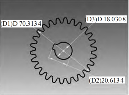
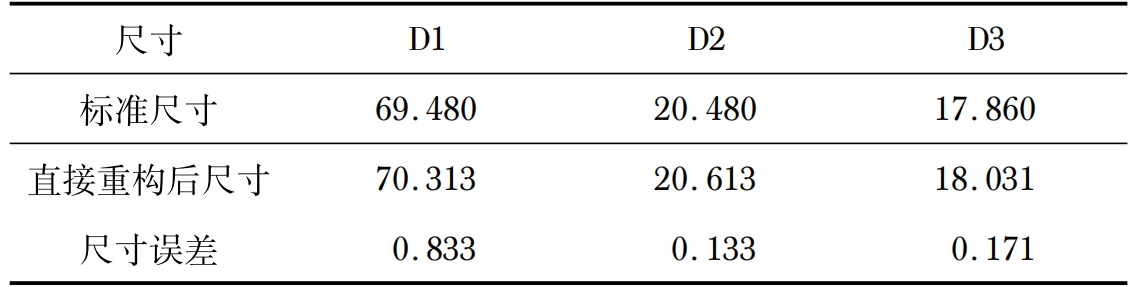
Obtain D1, D2, and D3 of the gear to be tested using a precision caliper with a 50 degree valueComparing the standard size with the directly reconstructed size reveals the measurement of D1 sizeError is 0.833mm, D2 measurement error is 0.133mm, D3 measurement errorIt is 0.171mm.
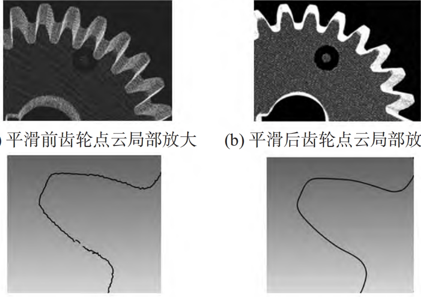
In order to improve the 3D point cloud reconstruction effect and size measurement accuracy of gears, the through filtering in section 2.1 is used to remove outliers from the initial point cloudUsing voxel grid filtering to remove redundant points while preserving features. filteringThe 3D point cloud result of the rear gear is shown in the figure, with an initial number of point clouds2974257, the filtered point cloud number is 215999, indicating that the filtering process canTo streamline the point cloud data of gears while preserving their surface features.
In order to reduce the surface roughness of the gear reconstruction model and improve the accuracy of the reconstruction size, polynomial based smoothing and moving least squares smoothing are used respectivelyProcess the 3D model reconstruction of the gear and obtain three dimensional data of the gearThe measurement error is shown in. After analysis, it can be concluded that the moving least squares method has been smoothed outThe gear size error is relatively small. Smooth image using moving least squares methodAs shown in the figure, after comparison, it can be seen that the smoothed point cloud is compared to the row before smoothingThe fabric is more tightly and orderly.
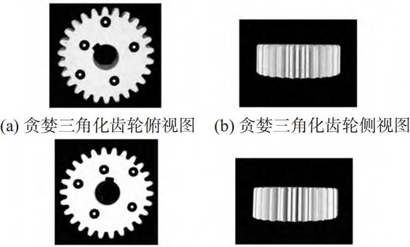
Using greedy triangulation algorithm for gear 3D point cloud reconstruction, where Figures (a) and (b) are directly reconstructed using greedy projection triangulation methodThe 3D model of the gear has significantly reduced holes, but the surface of the model still existsMany noise points and high surface roughness. Figures (c) and (d) show smoothed edgesUsing greedy projection triangulation algorithm to reconstruct the 3D model of gears, it can be seen from the graph that it is smoothThe surface reconstruction effect of the rear gear is better.
Using direct reconstruction and moving least squares to smooth direct reconstruction and smooth additionThe greedy triangulation method reconstructs the dimensions of gears D1, D2, and D3 obtained from three methodsThe measurement results and their measurement errors are shown in the table. After comparison, it can be seen that the smoothing and greedy methods are effectiveThe gear size reconstructed by the triangulation method has measurement errors compared to the other two methodsThe difference is small.
Conclusion
This article analyzes the initial three-dimensional point cloud characteristics of gears extracted by binocular vision systemsUsing direct filtering and voxel grid filtering respectively, outliers and redundant points in the initial 3D point cloud data of gears were removed; Researched based on mobile minimum twoA gear 3D reconstruction method using multiplication smoothing and greedy triangulation algorithm. BuiltExperimental platform for binocular vision gear measurement system, conducting measurement of spur cylindrical gearsExperiments were conducted to analyze gears through 3D point cloud data processing and model reconstructionParameter size measurement results and their errors. The experimental results indicate that using mobile is the most effective methodReconstructed gear 3D model table using small two multiplication smoothing and greedy triangulation algorithmSmooth surface and clear edges, with a measurement error of D1 size reduced from 0.833mm to0.544mm, D2 decreased from 0.133mm to 0.106mm, and D3 decreased from 0.171mmReduced to 0.148mm, solved the problem of surface roughness in gear 3D point cloud reconstruction modelThe problem effectively improves the reconstruction accuracy of gear 3D point cloud.