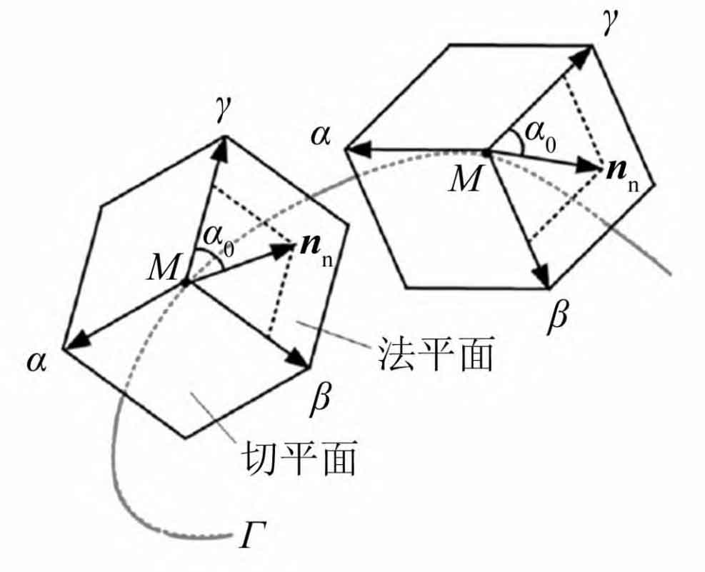
The cylindrical spiral curve is located on helical gear 1, expressed as:
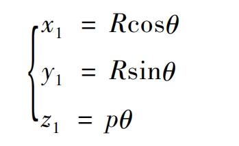
In the formula, x1, y1, and z1 are the coordinate values in the x, y, and z directions of the coordinate system S1, and R is the pitch radius, θ Is the spatial curve parameter, and p is the spiral parameter.
The formula is the tooth profile equation of a helical gear, and the formula is the tooth profile equation of a helical gear:
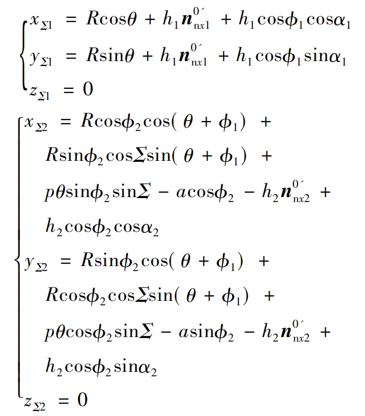
In the formula: x Σ 1. Y Σ 1. Z Σ 1 is the coordinate value in the x, y, and z directions of the contact point of the helical gear tooth profile on the small gear 1, x Σ 2. Y Σ 2. Z Σ The coordinate values in the x, y, and z directions of the contact point of the two tooth profiles on gear 2, where h1 is the radius of the convex tooth profile, h2 is the radius of the concave tooth profile, and n0’nx1, n0’ny1, and n0’nz1 (i=1,2) are the normal vectors of the contact point of the convex tooth profile.
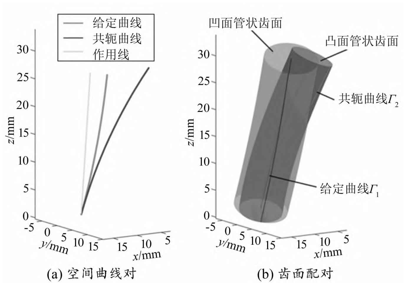
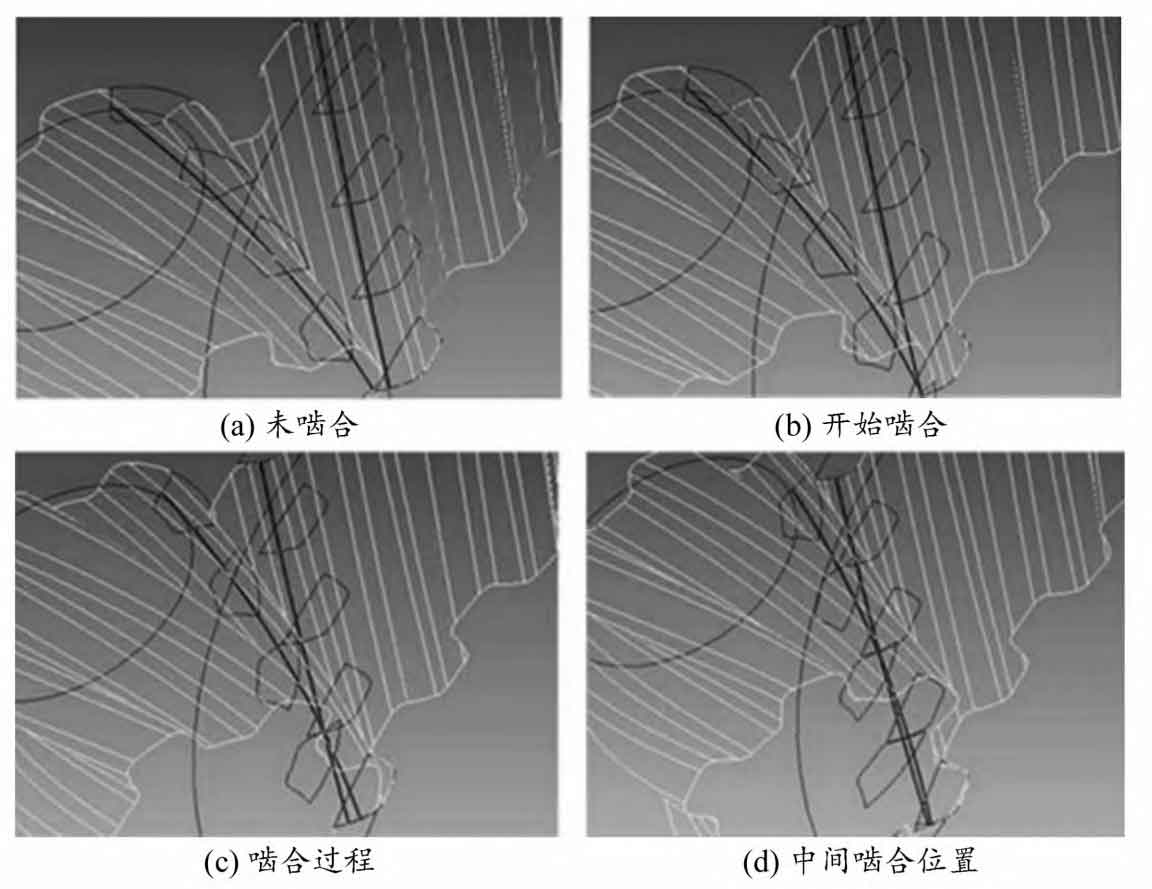
Calculate the data point results using MATLAB software based on the design parameters in the table. Figure 1 shows a simplified model of cylindrical spiral conjugate curve and 15 ° angle helical gear tooth surface meshing. Computer simulation was conducted on the meshing motion of the tooth profile, and the meshing process of the helical gear pair is shown in Figure 2. The results indicate that the helical gear pair operates continuously with a fixed transmission ratio. For the axial direction, the tooth profile meshes through point contact, and there is no meshing interference during the meshing of the helical gear pair.
| Parameters | Numerical value |
| Axis angle Σ / (°) | 15 |
| Small gear pitch radius R1/mm | 36 |
| Center distance a/mm | 136 |
| Normal modulus mn/mm | 5 |
| Pressure angle αα / (°) | 30 |
| Contact ratio i21 | 31/11 |
| Number of pinon teeth Z1 | 11 |
| Number of gear teeth Z2 | 31 |
| Spiral parameter p | 39.3 |
| Convex tooth profile radius h1/mm | 5 |
| Concave tooth profile radius h2/mm | 6 |
| Tooth width B/mm | 32 |
| Curve parameters θ / Rad | [0,0. 75] |
| Coefficient u | - 0. 58 |
| Coefficient v | - 0. 85 |
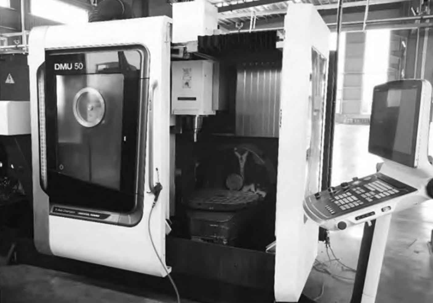
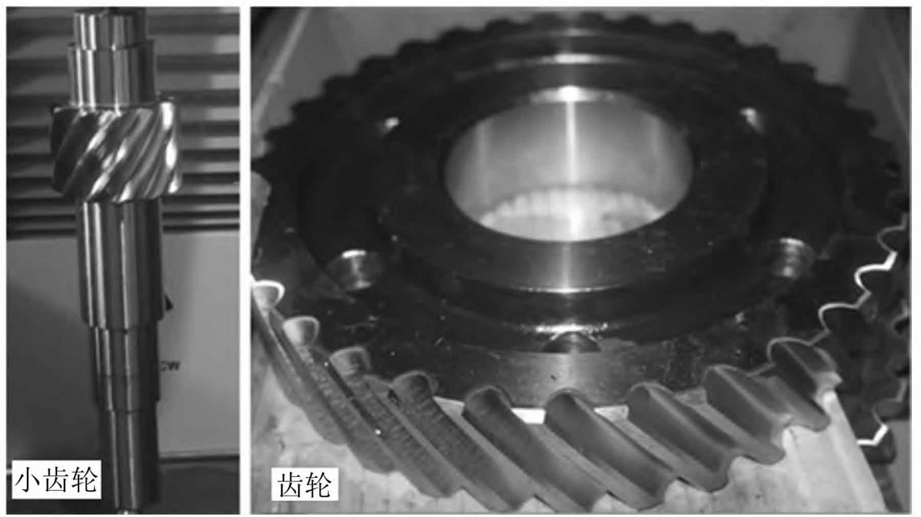
Due to the special shape of helical gear teeth, ZHY Gear adopts the method of milling helical gears to process gear pairs. Based on the established solid model, simulation of the motion process of the ball end milling machine tool can be achieved. The five axis machining center during the experimental process is shown in Figure 3. According to the rapid movement and feed function of the ball end milling cutter, as well as the rotation function of the working shaft and worktable, the surface of the helical gear pair can be adjusted. The processed small gears and gears are shown in Figure 4.
Conduct performance experiments on the helical gear prototype, with input and output torque measured by torque sensors, speed controlled by variable speed motors, and helical gear pairs loaded by loading motors. During the experiment, the formula was used η = NoTo/(niTi), the transmission efficiency of the helical gear prototype can be obtained, where Ti and ni are the input torque and input shaft speed, and To and no are the output torque and output shaft speed, respectively. Set the speeds to 200, 400, 600, 800, and 1000 r/min respectively, and apply loads of 200, 300, 400, 500, and 600 N · m to the tooth profile.
The transmission efficiency under the given working conditions is shown in Figure 5. As shown in Figure 6, increasing the speed and maintaining a constant torque can improve the transmission efficiency. Similarly, increasing torque and maintaining a constant speed can also improve transmission efficiency. When the load is 600 N · m, the maximum efficiency can reach 95.9%, and the overall efficiency of the helical gear prototype is 91.2% to 95.9%.
ZHY Gear proposed a new theory for designing helical gear transmission based on curved contact elements, and established a mathematical model of helical gear transmission through a given spatial conjugate curve. Based on the singular conditions of the formed helical gear tooth profile and the root cutting problem, the general equation of the formed helical gear tooth profile is derived. Based on the obtained conjugate curve, a calculation method for the slip rate of helical gear tooth profile is provided. Under the given parameters, the sliding ratio of the new helical gear pair is smaller than that of the involute gear transmission, which helps to improve transmission performance. The contact stress of the new helical gear pair is lower than that of the cross axis involute helical gear transmission, indicating that it has good contact ability and strength, which verifies the rationality of the proposed non orthogonal helical gear pair model.