
The diesel engine, as the main power source of vehicles, plays a very important role in the development of the national economy. The power transmission of diesel engines includes belt transmission, gear transmission, chain transmission, etc. The gear transmission structure is compact, and under the same power and transmission ratio conditions, the gear transmission structure is much more compact than other transmission forms. At the same time, it has a wide range of applications, can meet the different requirements of various machines, can transmit a wide range of power, can ensure a constant transmission ratio, and high mechanical efficiency, generally up to 0.90 to 0.98.
The gear transmission system is widely used in diesel engines, especially with significant advantages for camshaft mounted diesel engines. In order to better ensure the good operation of diesel engines, many scholars have improved and optimized the gear system.
The geometric error of gears is one of the important impacts of vehicle noise. Liu Shihao proposed a method for predicting gearbox noise through geometric errors by considering tooth surface modeling, contact analysis, vibration simulation, and acoustic simulation.
Discussed the impact of gear geometric errors on each link. Guo Xin et al. analyzed the effect of backlash on gear knocking noise of a six cylinder diesel engine’s spur cylindrical gear, and proposed an optimization scheme of using shear gears instead of intermediate transition gears in the gear system. Zeng Xiaochun et al. established a dynamic model of the timing gear system considering the flexibility of the timing gear support system in response to the whistling phenomenon of the timing gear in a certain diesel engine. They analyzed the transmission error, contact spots, and vibration contribution of each gear pair, and proposed a gear modification scheme to control the surface machining quality of the tooth surface. Based on the actual working conditions of diesel engine crankshaft gear assembly, the influence of gear assembly interference on gear stress was obtained, and a method to improve gear stress distribution was obtained by comparing the calculation results with those of increasing groove models. A. Amani, C. Spitas et al. pointed out that as the volume of gear systems gradually tends towards miniaturization, people shrink gear systems by increasing their load-bearing capacity.
This study mainly focuses on the design of gear transmission system for 4105 diesel engine, including crankshaft gear, camshaft gear, idler gear, oil pump gear, etc. The camshaft gear, timing idler gear, and fuel injection pump timing gear are all driven by the crankshaft timing gear. The transmission ratio between the crankshaft timing gear and the fuel injection pump timing gear and camshaft gear is 2:1. Subsequently, the installation marking positions of each gear were calculated to ensure the good operation of the gear system.
1. 4105 diesel engine parameters
The 4105 diesel engine is an inline, water-cooled, turbocharged four cylinder diesel engine. The diesel engine has a cylinder diameter of 105mm, a stroke of 127mm, a compression ratio of 18.5, a maximum torque of 457.7N · m, a rated power of 100kW, and a speed of 2400r/min.
2. Gear system design
2.1 Calculation of gear tooth count
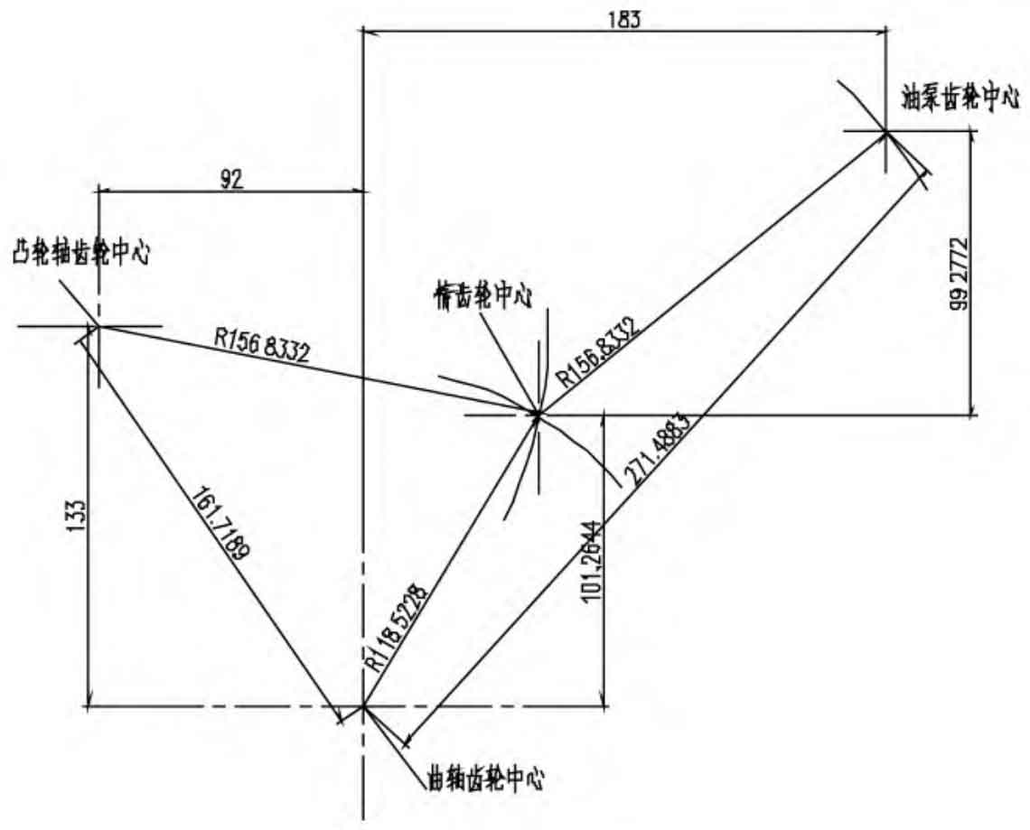
The center positions of the crankshaft gear, camshaft gear, idler gear, and oil pump gear have been determined on the engine body. The center distance of each gear is shown in Figure 1. In order to meet the strength requirements, the module of each gear is selected to be 2.25, and the number of teeth of the crankshaft timing gear is 32. Therefore, based on the relationship between the transmission ratio i curve/i spray=i curve/i convex=z spray/z curve=z convex/z curve=2/1, it can be determined that the number of teeth in the fuel injection pump gear and camshaft gear is 64.
Calculation of the number of teeth for the idler gear:
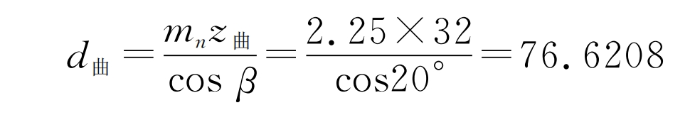
From Figure 1, it can be seen that the center distance between the crankshaft timing gear and the idler gear is a=118.5228.
Therefore, the number of teeth of the idler gear z is taken as 67.
2.2 Gear Design
(1) Crankshaft gear
Figure 2 shows the dimensions of the crankshaft gear and timing gear, with the spiral direction being left rotation. Mainly made of steel materials. Features: In order to withstand the constantly changing gas pressure, inertia force, and centrifugal force generated during rotation, it is required to have sufficient strength and stiffness, wear resistance, good lubrication, reliable installation and fixation, and axial positioning or limitation of axial displacement. In addition, the layout of the crankshaft should be reasonable to meet the requirements of the ignition sequence and smooth operation of the diesel engine. Function: Installed at the front end of the crankshaft, it is used to drive the timing idler gear, thereby driving the camshaft gear and fuel injection pump timing gear, while ensuring the valve timing phase during engine operation, so that the opening and closing of the intake and exhaust valves are consistent with piston movement. Material: 20CrMnTi. After carburizing and quenching, the surface hardness of the crankshaft timing gear can reach 58-63HRC, and the core hardness can reach 32-42HRC.
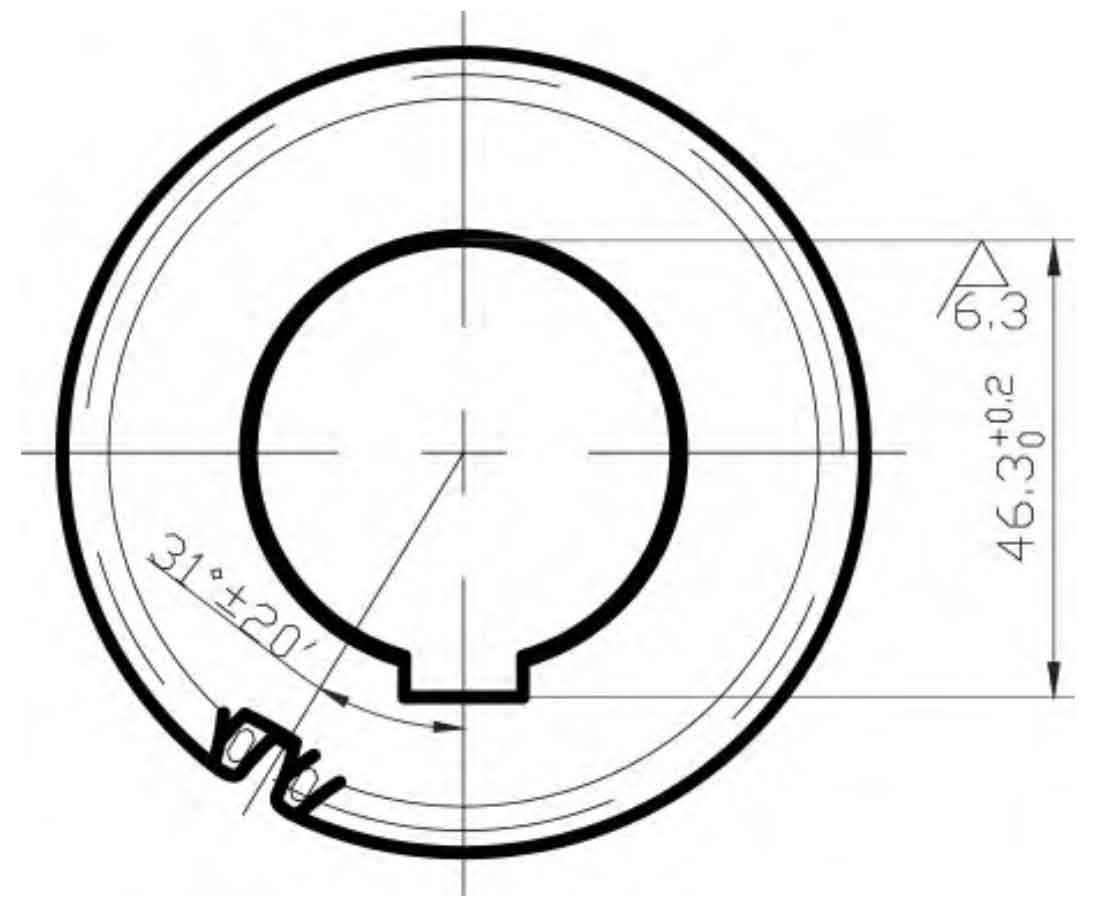
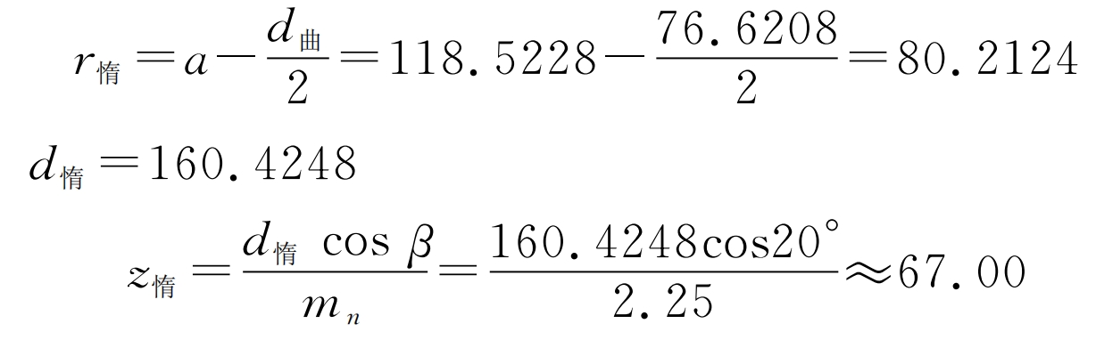
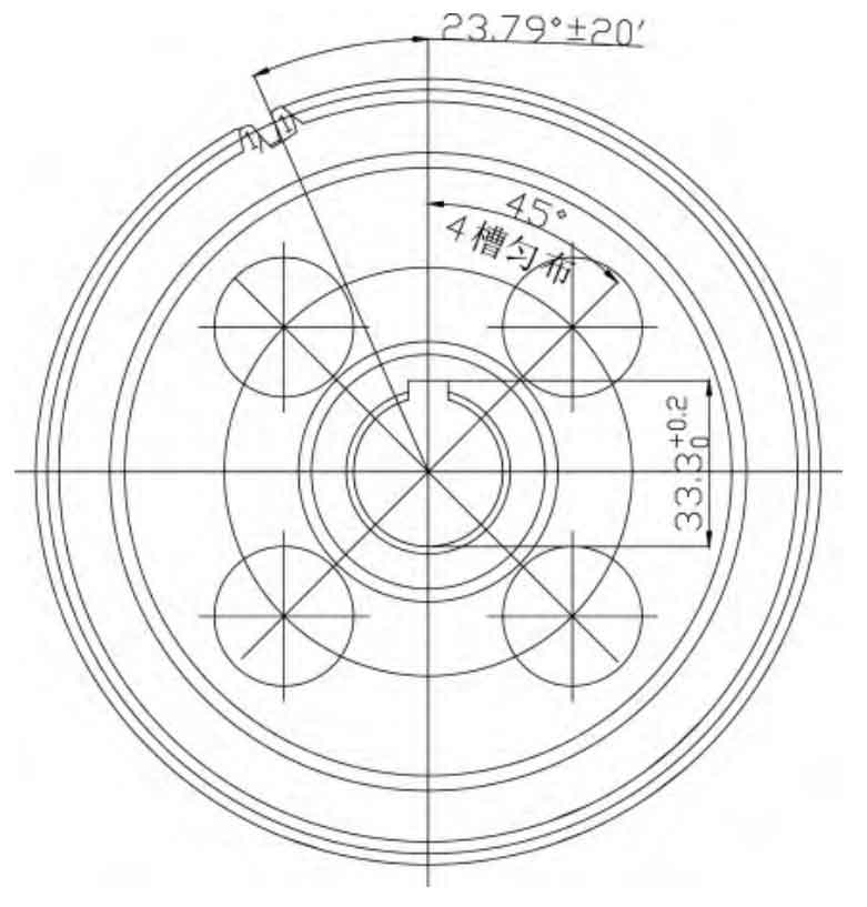
(2) Camshaft gear
The size of the camshaft gear is shown in Figure 3, and the spiral direction is left-handed. Mainly made of cast iron or cast steel materials. Features: The camshaft is equipped with intake and exhaust camshafts, which are installed on the cylinder block with two end journals of each group of valves, and one end is equipped with a timing gear. To prevent axial displacement of the camshaft, a retaining ring is installed between the first journal end face and the timing gear hub; The camshaft axis is equipped with an oil passage that is connected to the journal, and attention should be paid to aligning the oil hole during assembly. Function: Drive the camshaft and machine a convex cam shape on its surface to achieve the purpose of controlling the opening and closing of the intake and exhaust valves. Material: 42CrMo. After quenching and tempering treatment, the surface hardness of the hydraulic pump gear can reach 26-32HRC, and after nitriding treatment, the tooth surface hardness can reach 550HV1.
(3) Fuel injection pump timing gear
The fuel injection pump is the core component of the engine, and its main power comes from the crankshaft. The force of the crankshaft gear is transmitted to the oil pump gear through the idler gear, which drives the oil pump to pump oil in one go. The meshing between the oil pump gear and the idler gear bears complex dynamic loads such as repeated contact stress, bending stress, and even impact stress under the action of pulse alternating stress. If there are problems in any stage of gear design, manufacturing, processing, assembly, and use, it may cause systematic errors and lead to various quality accidents.
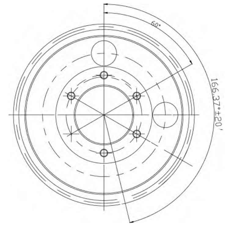
The timing gear size of the fuel injection pump is shown in Figure 4, and the spiral direction is left rotation. Mainly made of cast iron or cast steel materials. Function: Drive the fuel injection pump to provide timing. Material: 20CrMnTi. After carburizing and quenching, the surface hardness of this material can reach 58-63HRC, and the core hardness can reach 32-42HRC.
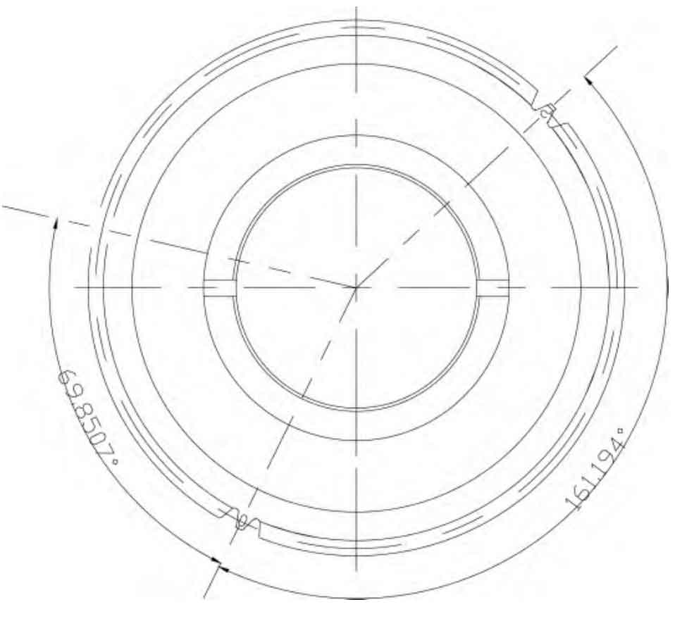
(4) Timing Idler Gear
The size of the timing idler gear is shown in Figure 5, and the spiral direction is right-handed. Features: The tooth shape is the same as that of ordinary gears; Part of the teeth have gaps left; Unable to actively transmit power. Function: It is to make the rotation direction of the fuel injection pump gear and camshaft gear be the same as the crankshaft timing gear, and the idler gear is a transitional part of the gear system, which will not change the transmission relationship. It is only to make the gear system stress more reasonable or meet the layout of the entire transmission system. Therefore, it only changes the steering and cannot change the transmission ratio. Material: 20CrMnTi. After carburizing and quenching, the surface hardness of this material can reach 58-63HRC, and the core hardness can reach 32-42HRC.
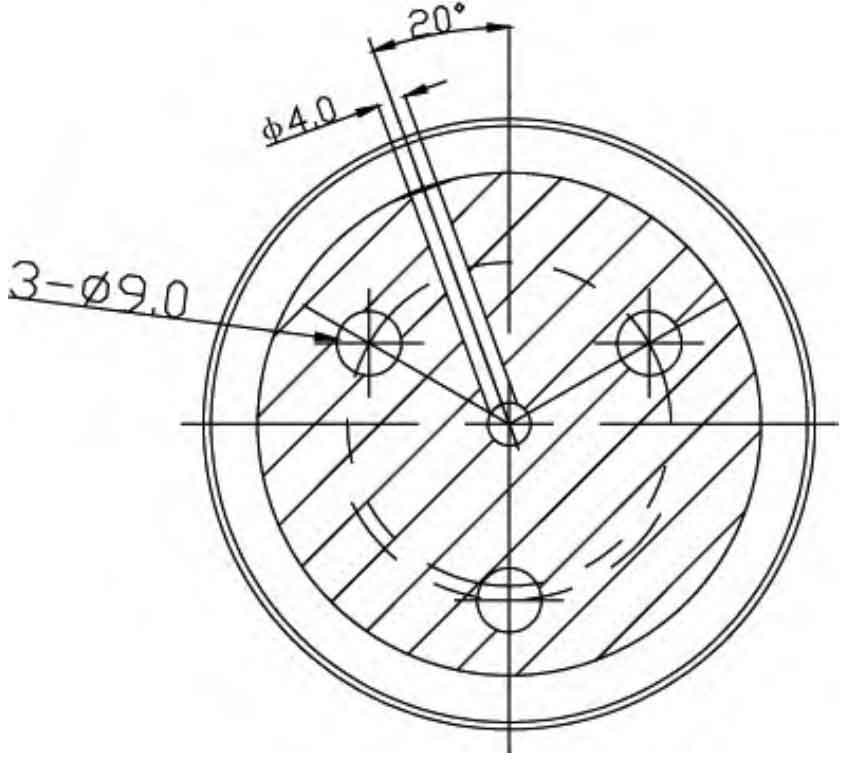
(5) Idler gear shaft
The idler gear shaft is a component used to support the timing idler gear, and both rotate together to transmit motion, torque, or bending moment. The material used is 45 steel. Idler gear shaft as shown in Figure 6, with three upper parts Φ A 9mm through-hole is used to install the idler gear shaft on the machine body; Φ The 4mm oil passage is used to lubricate the gears. In order to facilitate oil circulation, the oil passage should be offset by 20 ° from the center. The center hole at the top serves not only as a positioning function, but also as an oil passage.
3. Calculation of gear marking position
The positions of the camshaft gear, idler gear, and crankshaft gear are shown in Figure 7, and the center distance is the same as in Figure 1.
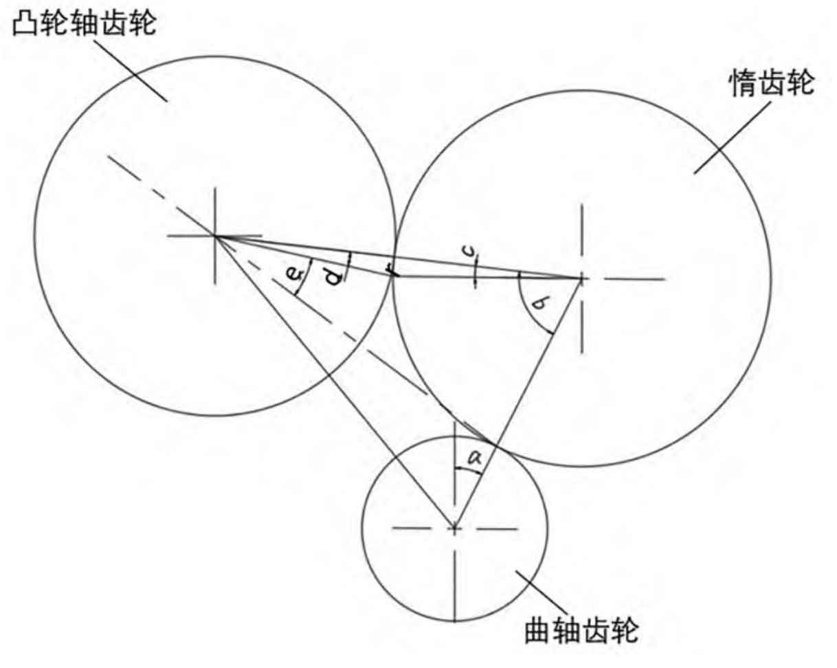
3.1 Calculation of marking positions for crankshaft gear, camshaft gear, and idler gear
The center distance a1 between the crankshaft gear and the idler gear is:
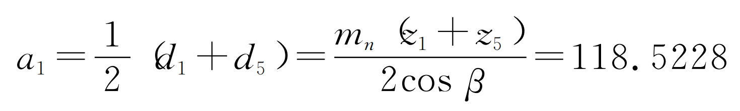
The center distance between the crankshaft gear and the camshaft gear is a2=161.7189;
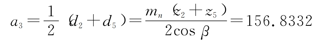
The center distance a3 between the idler gear and the camshaft is:
The vertical distance between the idler gear and the crankshaft gear is d=101.2644.
The angle a between the marked position of the crankshaft gear and the keyway:
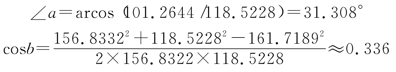
∠b=70.367°;
70.367/(360/67)=13.096;
The number of teeth corresponding to 70.367 ° on the idler gear is 13.096, rounded to 13.
The angle of 13 teeth on the idler gear should be: 13 × (360/67)=69.8507 °;
So, the angle between the marks on the idler gear and crankshaft gear and the marks on the idler gear and camshaft gear is 69.8507 °.
The indexing radius of the idler gear and camshaft gear is 80.2124 and 76.6208;
∠c=70.367°-69.8507°=0.5163°;
The distance between the center connecting line of the idler gear and the camshaft gear and the meshing point of the two gears is r.
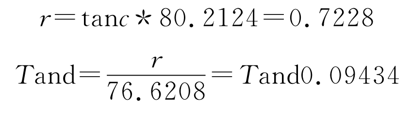
∠ d=0.5405 °;
The keyway angle between the crankshaft gear and the camshaft gear is 53.991 °;
The angle e between the keyway of the camshaft gear and the marked position;
∠ e=180 ° -70.367 ° -31.308 ° -53.991 ° -0.5405 °=23.7935 °
3.2 Calculation of Idler Gear and Oil Pump Gear Mark Positions
The positions of the oil pump gear, idler gear, and crankshaft gear are shown in Figure 8, and the center distance is the same as in Figure 1.
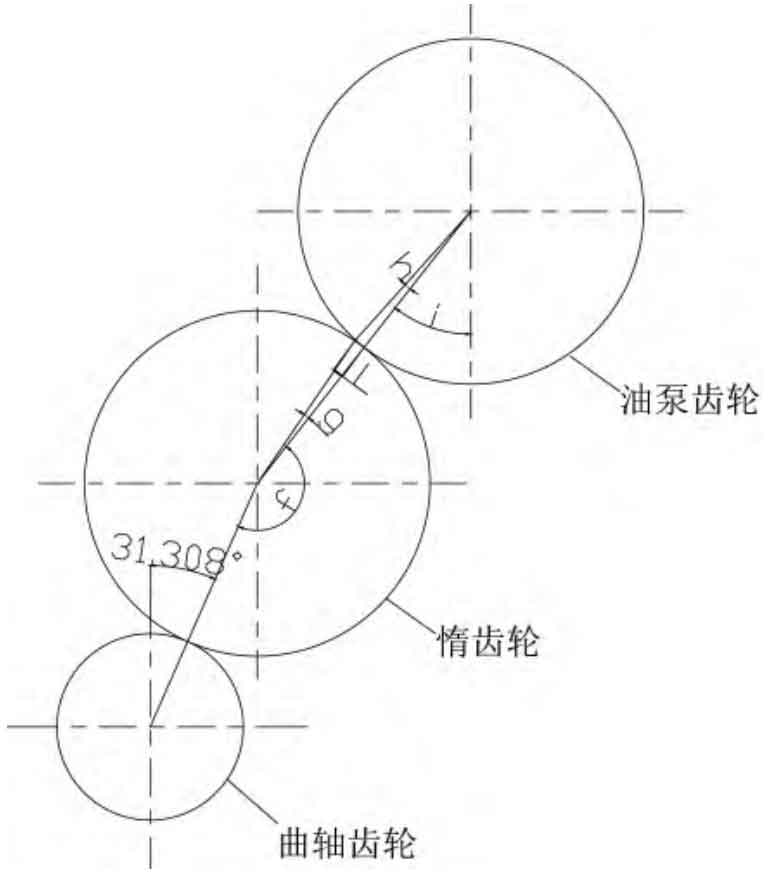
The center distance between the crankshaft gear and the idler gear is 118.5228; The center distance between the crankshaft gear and the oil pump gear is 271.4883; The center distance between the idler gear and the oil pump gear is 156.8332. The vertical distance between the idler gear and the oil pump gear is 99.2772.
∠ f=160.58 °;
Number of teeth on the idler gear at 160.58 °: 160.58/(360/67)=29.9;
Take the number of teeth on the idler gear as 30;
So the angle between the “crankshaft gear and idler gear marking point” and the “idler gear and oil pump gear marking point” is:

30 × (360/67)=161.194 °;
∠ g=161.194 ° -160.58 °=0.614 °;
The radius of the indexing circle for the idler gear and oil pump gear is:
80.2124 and 76.6208;
The distance between the center connection line of the idler gear and the oil pump gear and the meshing point of the two gears is L.
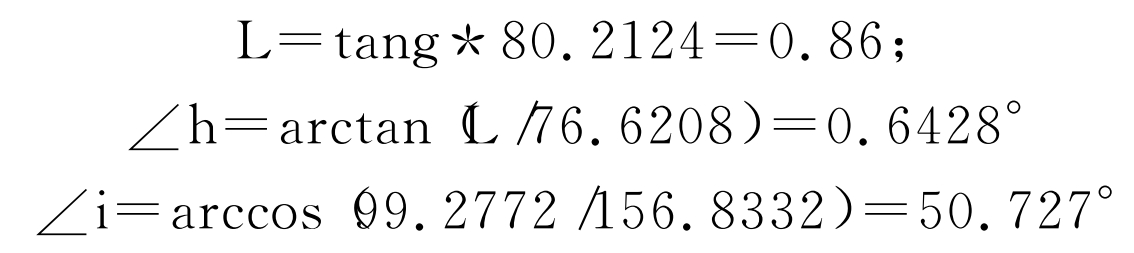
The angle between the keyway of the oil pump gear and the marked position is: 180 ° -65 °+50.727 °+0.6428 °=166.3698 °.
4. Conclusion
ZHY Gear mainly designs the gear system of the 4105 diesel engine, including crankshaft timing gear, timing idler gear, camshaft gear, fuel injection pump gear, etc. Based on the center hole position of the gear provided on the body, the material, modulus, number of teeth and other parameters of each gear are designed, and relevant 2D gear drawings are drawn. In order to ensure the correct assembly of each gear, the marked positions of each gear were designed and calculated, and the angle between the keyway of the crankshaft, camshaft gear, oil pump gear and the marked positions, as well as the relationship between the marked positions of the idler gear, crankshaft gear, camshaft gear, etc., were obtained. The design of the 4105 diesel engine gear system provides theoretical support for the development of the 4105 diesel engine.