
During the flight of a certain aircraft, the N2 speed indicator was zero, causing a single engine to come to an air stop. Upon landing, the aircraft’s lubricating oil accessories were immediately inspected, and it was found that there were many small metal chips in the oil filter of the lubricating oil accessories and metal chip foam signal. After energy spectrum analysis of the metal chips, it was confirmed that they belonged to low alloy steel and had a carbon nitrogen co infiltration layer structure. Therefore, it is suspected that there is gear wear. The material grade of the driving gear and driven gear is 12Cr2Ni4A steel, and the surface is treated with carbon nitrogen co infiltration. On site disassembly of the N2 speed sensor mounting seat of the lubricating oil accessory revealed severe wear and partial tooth breakage faults in the driving and driven gears. In order to determine the nature and causes of the failure of the driving and driven gears of the N2 sensor, an analysis and discussion were conducted.
1. Analysis process
1.1 Appearance inspection
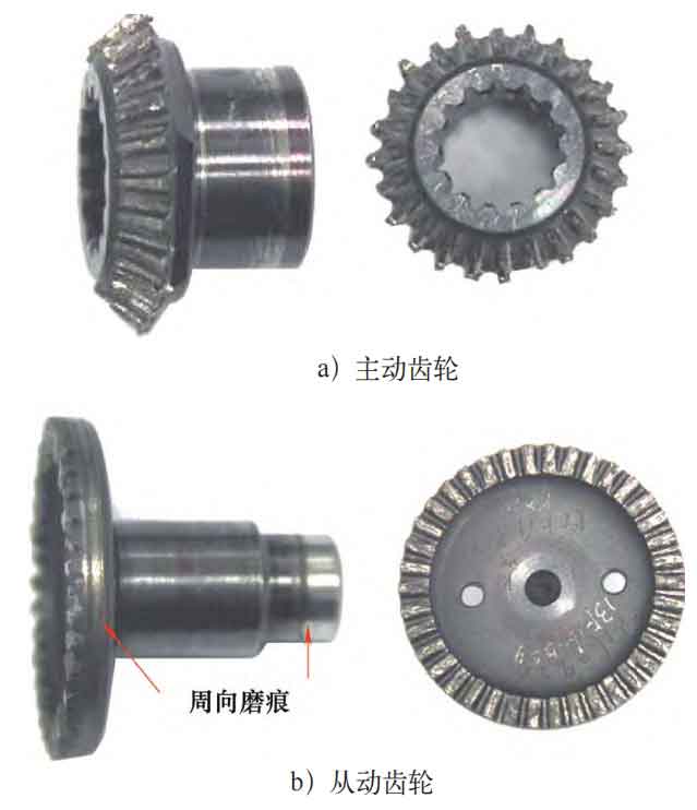
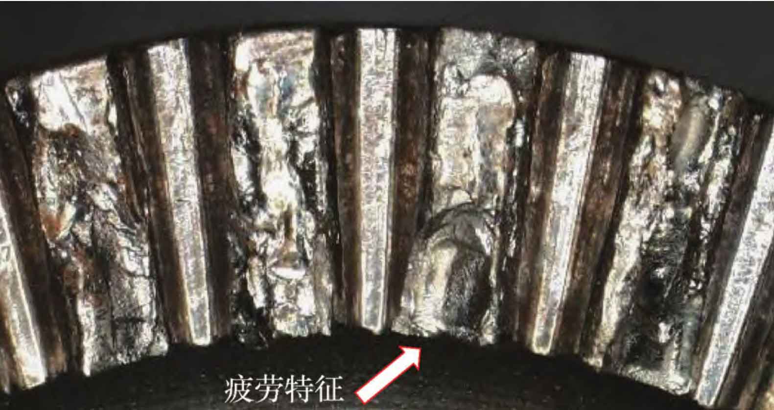
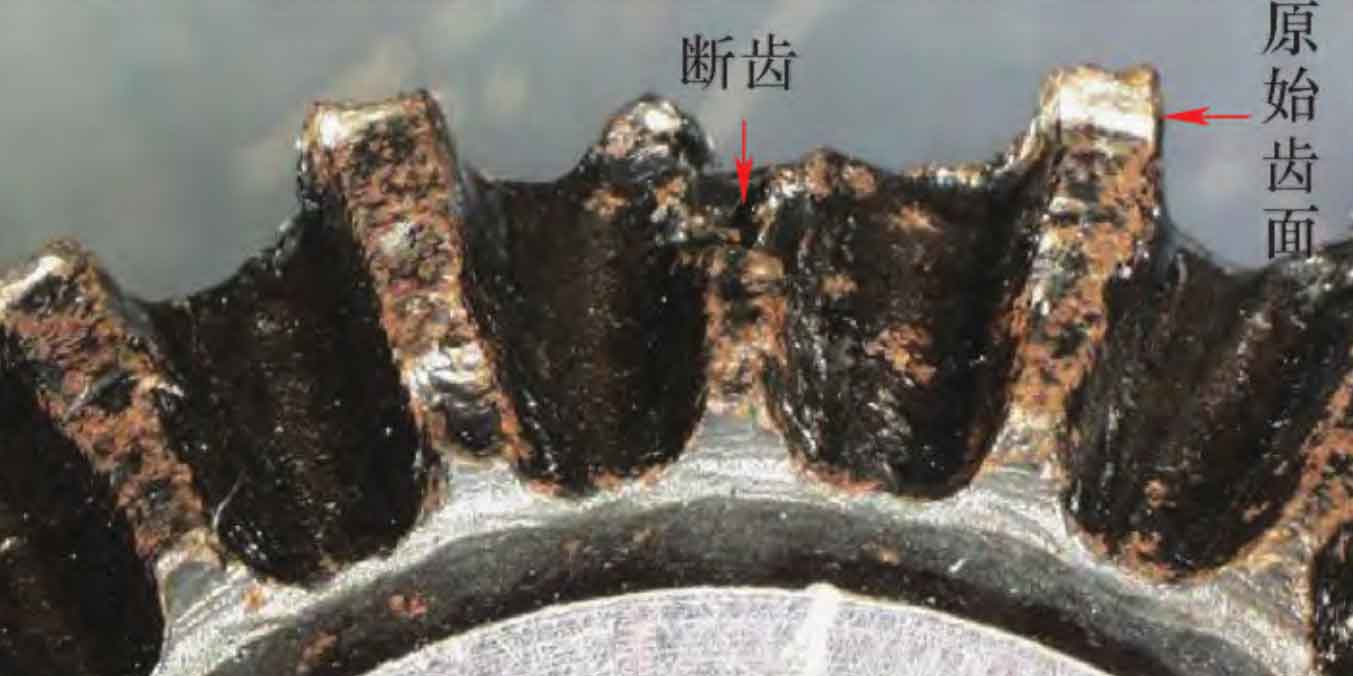
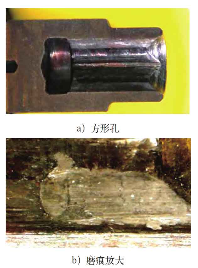
The appearance of the faulty gear is shown in Figure 1. From Figure 1, it can be seen that both the driving gear and the driven gear teeth have extensive wear, and circumferential wear marks can be seen on the side walls of the driven gear. Out of the 38 teeth of the driven gear, 33 teeth had tooth tips that had fallen off, with most of the broken surfaces having significant fluctuations and severe wear. No fatigue features were observed on the remaining original fracture surfaces; A small portion of the falling blocks have flat fracture surfaces, and obvious radial edges and fatigue curves can be seen on the cross-section, as shown in Figure 2. The wear marks on the 5 teeth with no falling blocks at the top of the teeth are relatively minor. In addition, there are contact marks between the driven gear and the driving gear at the bottom of the teeth of the driven gear. The gear tooth indicated by the arrow in Figure 2 is a fatigue fracture tooth, which extends counterclockwise from the tooth surface near the tooth top to the tooth root. The fatigue extension zone shows fatigue arc characteristics, and the area occupied by the fatigue extension zone is relatively large. Therefore, it is judged that this gear tooth is the first fracture tooth. The wear marks on the top of the 24 gears on the driving gear are relatively uniform, with a wear depth of about 0.5mm. There are contact meshing marks at the bottom of the teeth. In addition, 5 tooth roots of the driving gear fractured, with uneven and severely worn fracture surfaces, making it impossible to observe the microstructure of the fracture surface, as shown in Figure 3. After inspecting the shaft end cut of the driven gear, it was found that there were axial compression wear marks on the mating surface between the square hole and the pin shaft, as shown in Figure 4.
1.2 SEM analysis
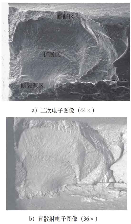
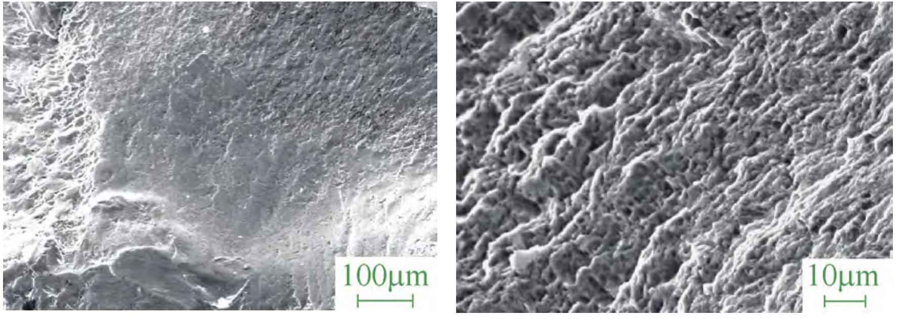
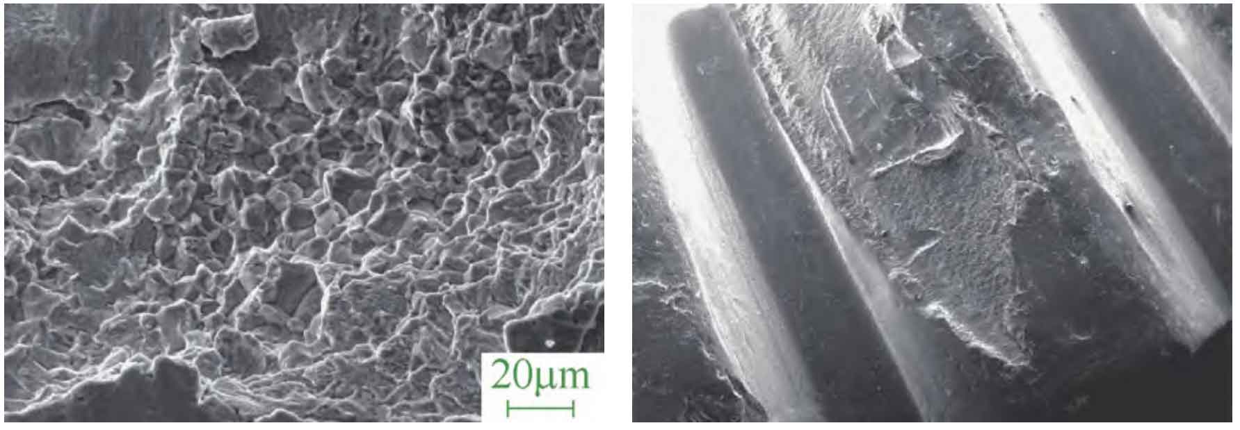
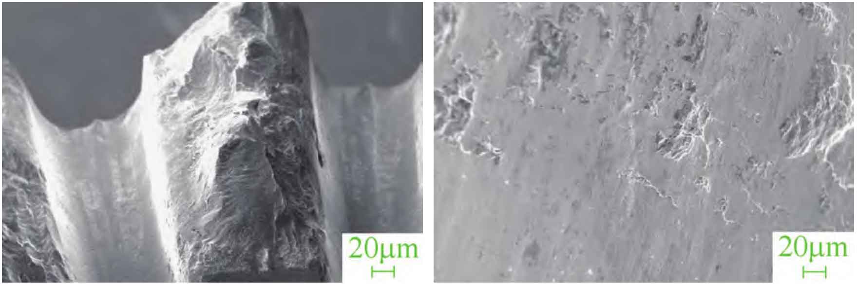
Through comparative observation, the microstructure of the first broken tooth of the driven gear is shown in Figure 5. From Figure 5, it can be seen that there are obvious fracture source areas, extension areas, and instantaneous fracture areas on the fracture surface. Judging from the convergence trend of radial prisms and fatigue arcs, the fracture source area is a short line source located on the surface of the gear. The short line source indicates a high initial fatigue stress, and the microstructure is shown in Figure 6; The fatigue propagation zone is severely worn, with fatigue arcs and fine fatigue bands visible locally. The microstructure is shown in Figure 7; The area of the instantaneous fracture zone is relatively small, indicating that fatigue propagation is very sufficient and the propagation stress is small. This zone is located in the infiltration layer area, and the microstructure of the fracture surface is intergranular fracture, as shown in Figure 8. The micro morphology of the wear marks and falling blocks on the top of the driven gear teeth is shown in Figure 9, and the meshing marks with the driving gear can be seen at the bottom of the teeth, as shown in Figures 10 and 11. Energy spectrum analysis was conducted on the source area, and the main components were matrix elements. No abnormal elements were found, as shown in Table 1.
| Cr | Fe | Ni |
| 1.30 | 97.29 | 1.41 |
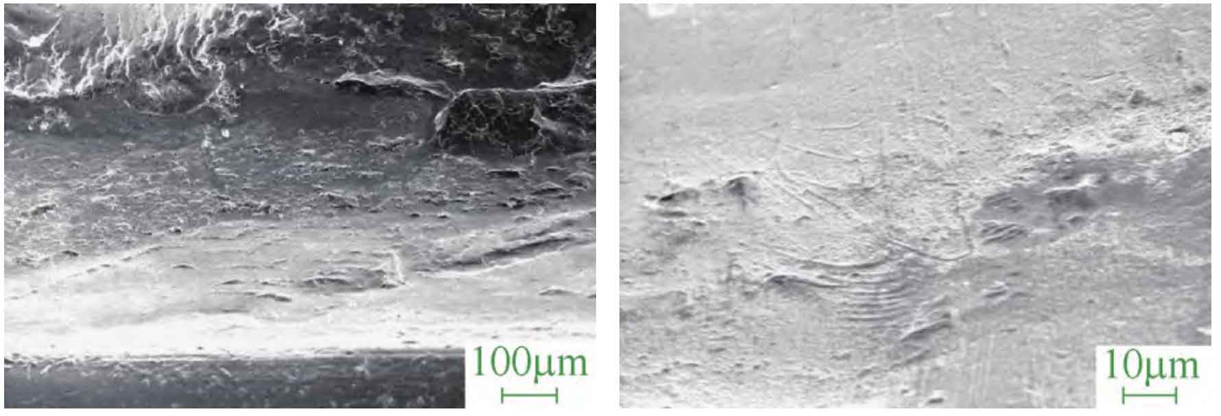
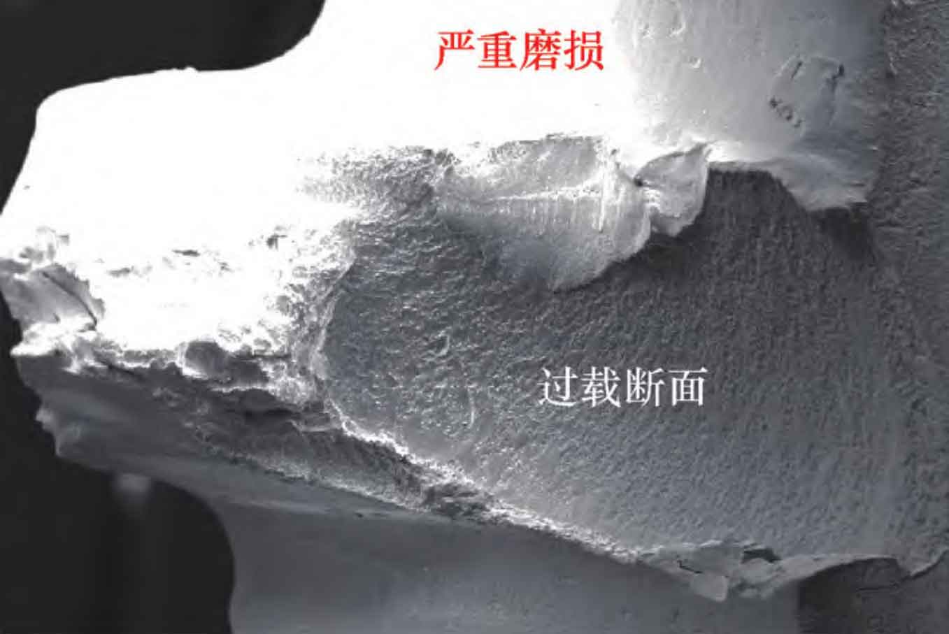
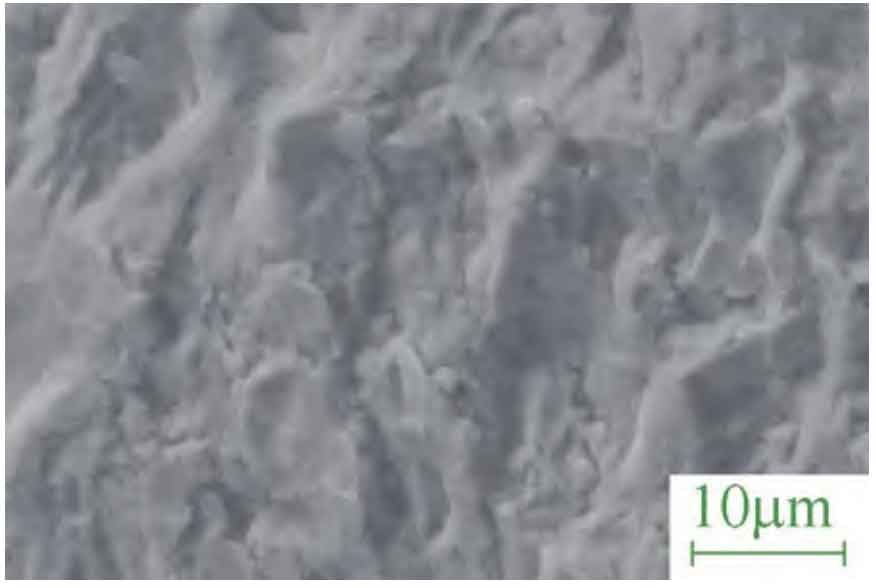
The 1/2 area of the fracture surface of the driving gear due to overload is severely compressed and worn, while the remaining 1/2 area is the overload fracture surface, as shown in Figure 12; The microstructure of the expansion zone of the overloaded tooth surface is a quasi cleavage morphology, as shown in Figure 13; The other teeth have similar morphology of compression wear, overload collapse, and are more severely damaged than the driven gear, as shown in Figure 14; The bottom surface of the driving gear teeth can be seen in contact with the top surface of the driven gear teeth, indicating poor coordination between the driving gear and the driven gear during operation, as shown in Figure 15.
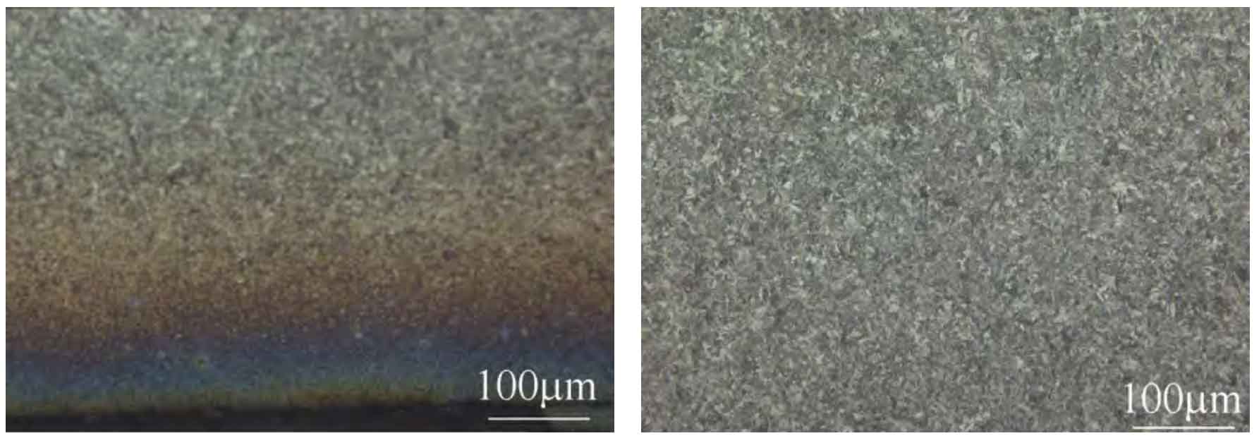
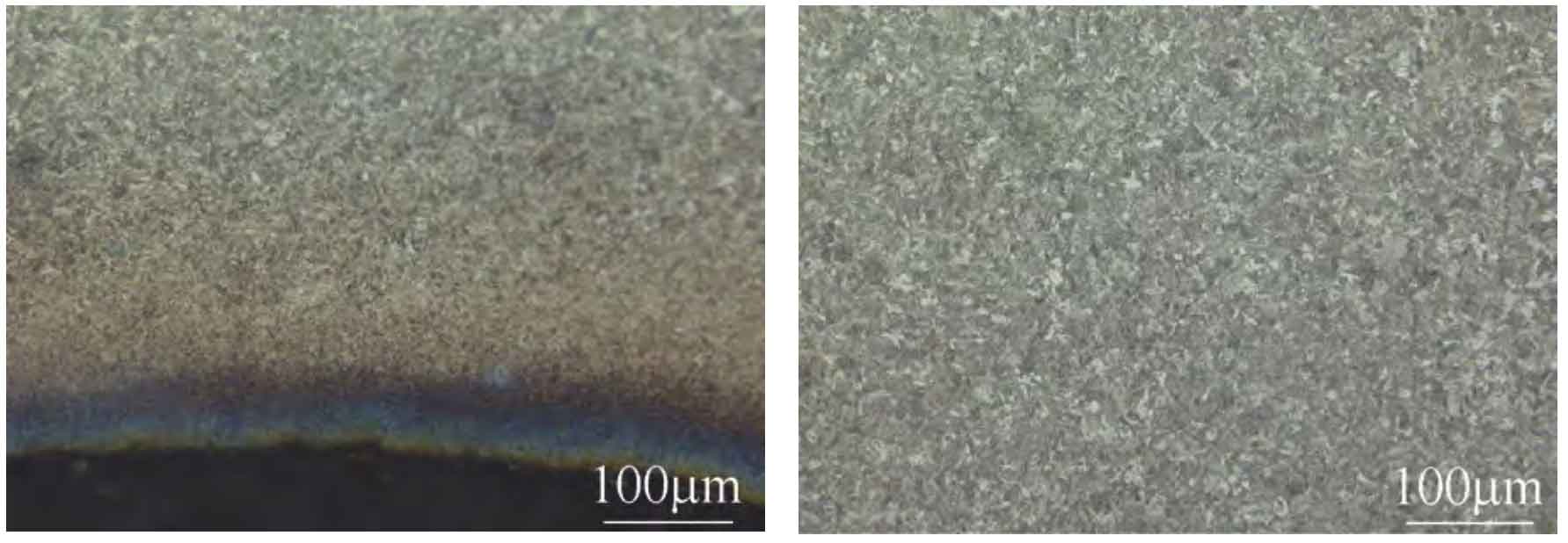
1.3 Metallographic analysis
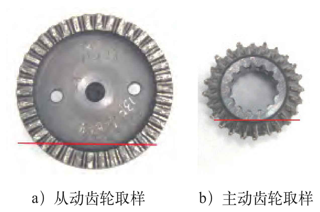
Cut metallographic samples from the teeth of the driving gear and the driven gear respectively, and the sampling positions are shown in Figure 16. After grinding, polishing, and corrosion observation, the microstructure and thickness of the carbon nitrogen co infiltration layer on the teeth of the driving gear and driven gear are uniform, with a small amount of residual austenite+hidden needle martensite in the structure, and tempered martensite in the center structure, which meets the relevant standards of the enterprise; The depth of the carbonitriding layer on the driven gear is 0.15~0.19mm, which meets the relevant standards of the enterprise. The tooth tip of the driving gear is severely worn, and the carbonitriding layer is incomplete, making it impossible to evaluate whether the original thickness of the carbonitriding layer meets the requirements. Therefore, no evaluation is conducted, as shown in Figures 17 to 20. The center microhardness (load 2.94N) of the driven gear and driving gear samples was tested, and the average microhardness was 436HV and 417HV, respectively, as shown in Table 2. When the standard requires a test load of 60kg (588N), the hardness ranges from 66 to 71.5HRA (319-410HV). Analysis suggests that due to severe gear wear and compression, the hardness may be slightly higher.
| Test points | 1 | 2 | 3 | 4 | 5 | Average |
| Driven gear | 429 | 437 | 440 | 438 | 435 | 436 |
| Driving gear | 420 | 413 | 415 | 419 | 418 | 417 |
2. Analysis and discussion
The above tests indicate that there are no material defects found in the driving and driven gears of the N2 sensor, and the infiltration layer structure and central structure meet the relevant standard requirements. Therefore, it can be determined that the cause of the two gears falling off is unrelated to the material. The driving gear of the N2 sensor has a smaller diameter and fewer gears compared to the driven gear, so the force frequency and speed are higher than those of the driven gear. The broken teeth of the driving gear fracture from the root, with uneven and severe wear on the fracture surface. The micro morphology of the non worn area is a quasi cleavage feature. The fracture surface of driven gears can be divided into two types: one type has relatively mild wear, with obvious fatigue source area, fatigue propagation area, and instantaneous fracture area visible. The fatigue source area is located on the surface of the gear and is a line source; Fatigue propagation is sufficient, with obvious fatigue arcs and fine fatigue bands visible; The proportion of instantaneous fracture zone is small, and the microstructure is characterized by intergranular features. The other type of wear is more severe, and no microscopic morphology of the fracture surface is observed.
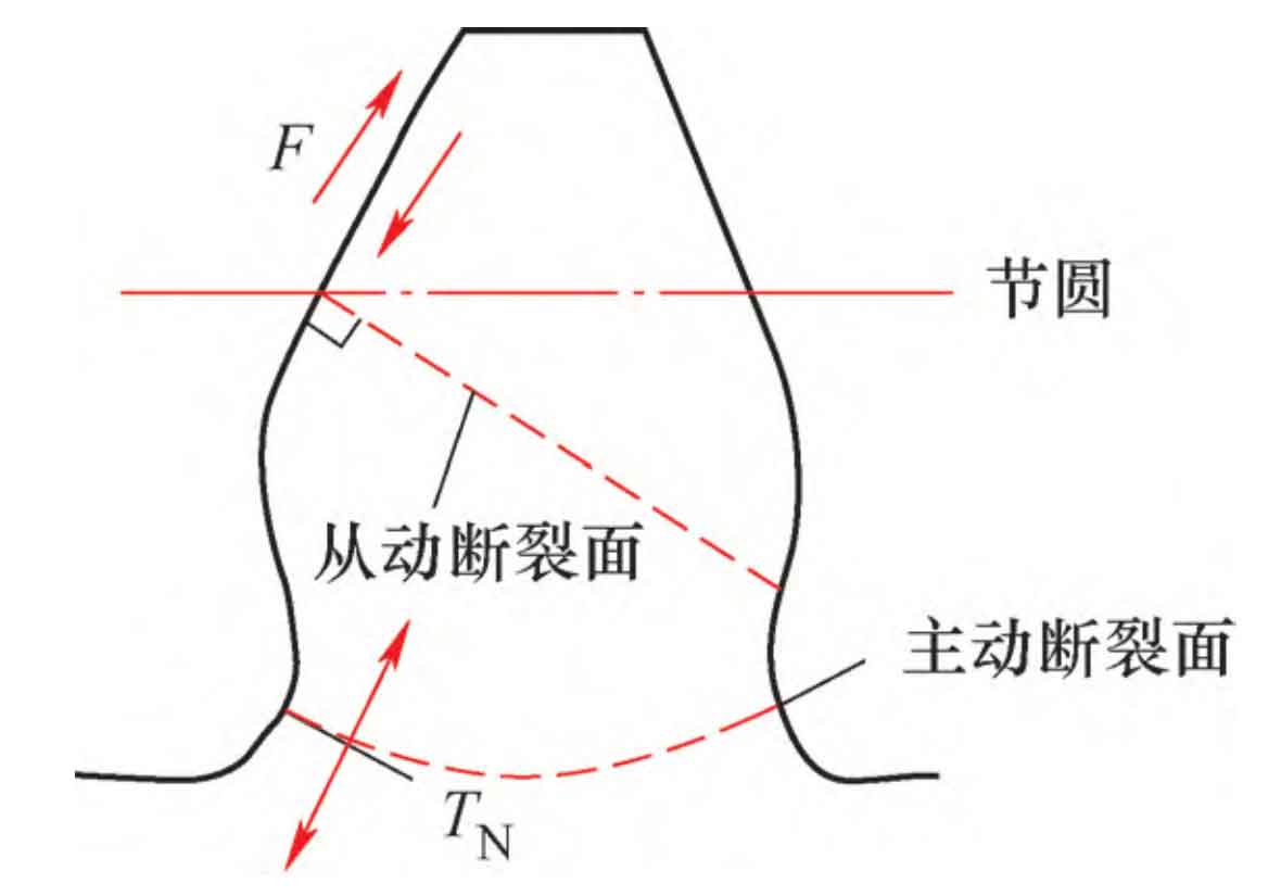
Based on the above test results, the analysis suggests that the failure nature of the N2 sensor gear in this engine is fatigue. Through re inspection, the assembly process meets the operational requirements. There are varying degrees of wear marks on the surface of the inner and outer steel sleeves of the gear shaft and bearings, as well as on the inner side of the transmission housing of the tachometer. These wear marks indirectly indicate that the gear is abnormal during operation, causing abnormal meshing of the tooth surface and resulting in contact fatigue peeling. After contact fatigue occurs, the peeling metal particles intensify the wear between teeth, further deteriorating the working environment. The peeling pits on the pitch circular working surface serve as the force points on the tooth surface and are also the weak links for crack initiation. After crack initiation, under the action of comprehensive stress (rolling, sliding, bending stress, vibration stress, etc.), they extend vertically along the working surface to the final fracture. The stress and fracture situation of the gear are shown in Figure 21.
In addition, due to the maximum bending stress of the gear teeth under load, it is located at the root of the tooth, and there is a significant stress concentration at the transition point R at the root of the tooth, making the root of the tooth R a weak link in the origin of gear cracks; Due to the fact that gears are subjected to force during meshing and not when disengaged, the bending stress on the teeth of the gears is pulsating stress; Under the repeated action of high bending stress, fatigue cracks are generated at the root of the tooth and gradually extend to the entire tooth fracture. The fractured teeth of the driving gear belong to this fracture mode. For the driving gear, the root of the tooth takes priority over the tooth surface for cracking, indicating that its stress concentration level is larger than the fatigue peeling pit on the tooth surface. Conversely, cracking occurs first from the peeling position on the tooth surface, such as the fracture of the driven gear.
3. Conclusion
1) The materials and heat treatment indicators of the driving and driven gears of the N2 sensor for inspection meet the technical requirements.
2) The reason for the failure of the driving and driven gears is fatigue fracture and wear caused by abnormal matching.