In modern industrial production, mechanical equipment is developing towards large-scale, complex, and automated aspects. Due to the complexity of the system, harsh working environment, and high failure rate, the large-scale mining spur gear transmission system directly affects the economic benefits of the enterprise once it fails. Therefore, in order to avoid transmission system failures and improve system reliability, it is necessary to design the system more comprehensively in terms of dynamic characteristics. The traditional design method has a complex process and often relies on experience. In order to improve the efficiency, systematicity, and completeness of design, it is necessary to optimize the multi-objective macroscopic parameters of the mining spur gear transmission system in the initial stage of designing large mining spur gear sets.
Domestic and foreign scholars have conducted extensive research on the dynamic optimization of macroscopic parameters for large-scale mining transmission systems, focusing on the establishment of dynamic models and the design of optimization models. Wang Yong et al. used the centralized mass method to model the dynamics of a single pair of spur gears, and optimized the random vibration and mass of the spur gear pair using genetic algorithm. Zhang Qingwei et al. established a centralized parameter model of a large mining spur gear system, and used the mixed discrete variable combination method to simultaneously optimize the vibration acceleration and system quality, reducing manufacturing costs and improving reliability. In summary, in previous studies on the optimization of spur gear systems, most have established a centralized mass method model, treating the shaft, bearings, and gears as elastic mass blocks with damping, which cannot predict the dynamic response of spur gears at different positions on the shaft, resulting in the inability to consider layout parameters for dynamic optimization of parallel axis spur gear systems. To this end, Neriya et al. first discretized the mass and stiffness of the shaft and conducted dynamic response analysis on the spur gear rotor system; Kuber et al. established a coupled dynamic model of a multi-stage shaft system and a multi mesh spur gear system, and analyzed the influence of inter stage phase angle on bearing dynamic load; Chang Lehao et al. used the generalized finite element method to establish a universal modeling method for fixed axis gear systems and boxes, and proved the effectiveness and accuracy of this method in solving the response.
To reduce the vibration and noise of spur gear systems, in the past, when establishing optimization models for macroscopic parameters of spur gear systems, the objective function was mostly to increase the coincidence degree of spur gears or directly use the noise empirical formula as the objective function. In Fu Xue Zhong, for the vibration and noise problem of spur gears, the objective function was to increase the fluctuation amplitude of spur gear meshing stiffness, The profile modification optimization of spur gears was carried out using loaded contact analysis (LTCA) and genetic algorithm. Cai Wenqi et al. focused on the two speed transmission system of an electric vehicle, with the optimization objective of maximizing the total overlap of involute spur gears. They optimized the macro parameters of the transmission spur gear pair and further conducted shape modification research. Jiang Chunming conducted multi-objective optimization on a three-axis four speed automotive transmission with the objective function of overlap and transmission system volume to improve the reliability of the transmission; Shao Zhengyu et al. optimized the design parameters of hyperbolic gears using the empirical formula for noise and the volume of spur gears as the optimization objective function. Although this type of objective function can reduce the stiffness excitation of spur gear systems, it does not consider the frequency relationship between complex systems and rotational speeds, which may weaken the optimization effect. For the dynamic optimization of spur gear systems considering frequency relationships, the objective function expression is often fitted by various parameters and the dynamic response obtained from the dynamic differential equation system, and the process is relatively complex, with relatively few research results. Qin Datong and others used the harmonic balance method to solve the dynamic response of large-scale mining transmission systems, with vibration acceleration as the objective function for optimization; Nie Huiyang established a centralized parameter model for the dual split spur gear transmission system, analyzed the load sharing coefficient and optimized it based on solving the dynamic response.
The above studies mostly use the concentrated mass method to establish dynamic models, which cannot predict the dynamic response of spur gears at different installation positions on the shaft, and there is relatively little analysis of the impact of different objective functions on the dynamic characteristics of the system. The amplitude of the dynamic meshing force of the spur gear pair is the main excitation source that causes the whistling problem of the spur gear system, and the volume of the transmission system is a reflection of the system’s economy. The two are often contradictory in design, To address such shortcomings, it is necessary to establish a comprehensive dynamic model and conduct multi-objective optimization. ZHY Gear focuses on the fixed shaft transmission system in a large mining spur gearbox as the research object. A macroscopic parameterized dynamic model is established using the generalized finite element method. Based on the NSGA ⁃ II optimization algorithm, an optimization model containing different objective functions is established, and the obtained dynamic response is compared and analyzed.
1. Establishment of parameterized dynamic model for secondary spur gear transmission
As shown in Figure 1, the two-stage large-scale mining spur gear transmission system consists of an input shaft, intermediate shaft, output shaft, two-stage spur gears, and three pairs of bearings. Taking the two-stage fixed shaft transmission system in a large mining spur gearbox as the research object, discretize it, establish parameterized dynamic models for each unit, and then parameterize the assembly of each unit dynamics according to different installation methods to achieve a mapping between the transmission system parameters and dynamic response. The mapping relationship can provide a dataset for optimizing the objective function fitting.
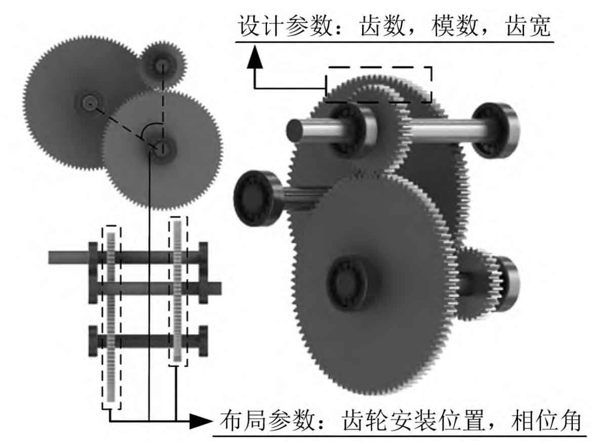
1.1 Parameterized modeling of axes
As shown in Figure 2, an 8-degree-of-freedom Timoshenko beam dynamic model is established, and its mass and stiffness sub matrices can be referred to in the literature. Overlay the sub matrices by nodes to form the overall stiffness matrix of the axis. Therefore, as shown in equation (1), under the premise of determining material properties, its overall stiffness matrix can be represented by the axial diameter parameter and axial length parameter of the shaft:

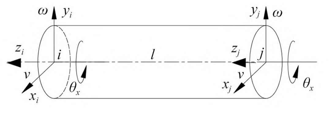
In the formula: ri is the axis radius, i=1, 2, 3; N is the axis length parameter, representing the number of discrete elements for the axis. To ensure the accuracy of the calculation results, the axis segment elements are set to 0.05m.
1.2 Parametric modeling of spur gears
As shown in Figure 3, establish an 8-degree-of-freedom spur gear meshing model, establish a differential equation system or formula based on the d’Alembert principle, and organize the stiffness matrix of the 8 × 8 meshing element:
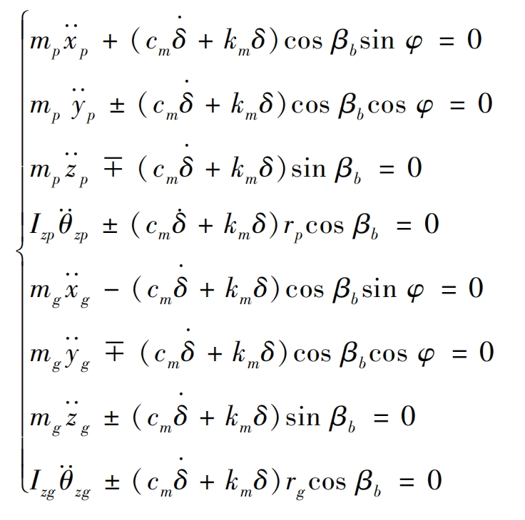
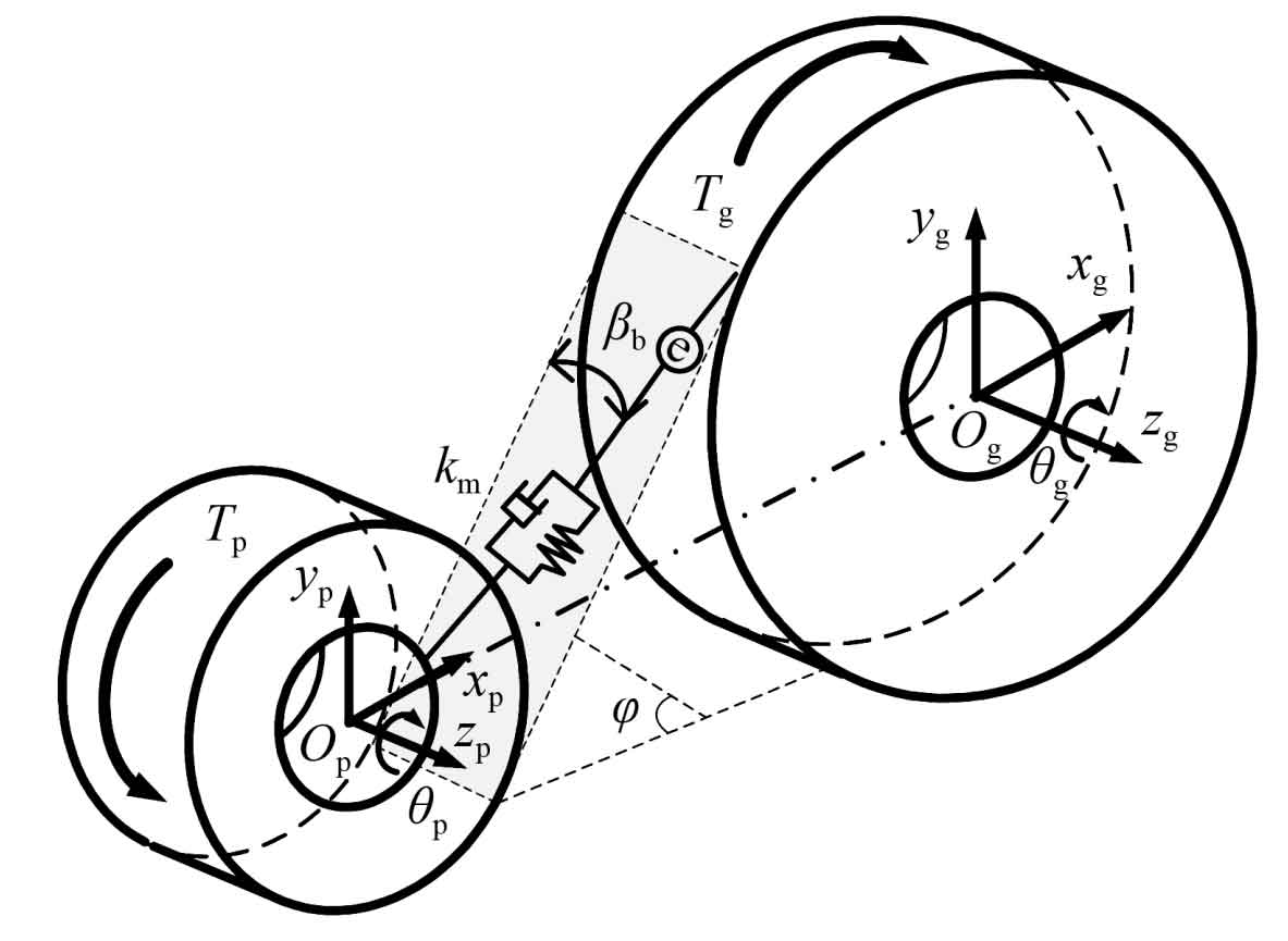
In the formula: mp/g is the main and driven gear mass; Izp/zg is the moment of inertia of the main and driven wheels around the z-axis; Cm is the meshing damping; Km is the comprehensive meshing stiffness; β B is the helix angle of the spur gear; φ Is the pressure angle of the spur gear.
The time-varying mesh stiffness km is solved using the potential energy method:
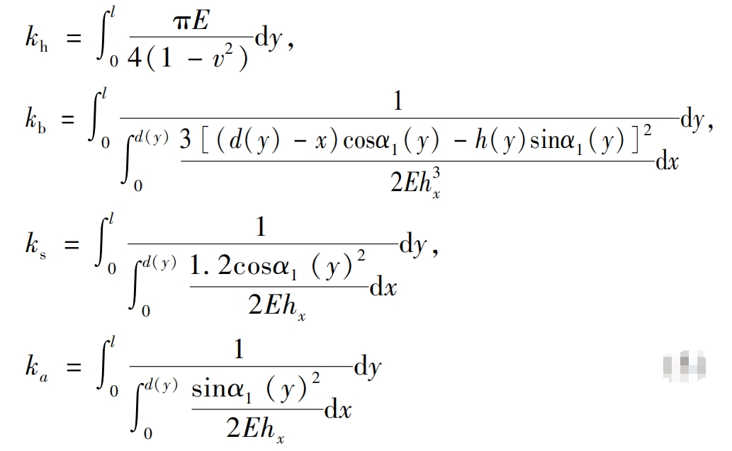
For each parameter, please refer to the references. Using the four potential energies mentioned above, calculate the Hertz stiffness kh, bending stiffness kb, shear stiffness ks, and radial compression stiffness ka respectively. At the same time, consider the flexible deformation of the spur gear base circle and calculate the corresponding stiffness.

The parameters in the formula depend on the number of teeth, and are secondary to the blade radius, pressure angle, and tooth top height. The specific calculation is obtained by polynomial fitting the coefficients in the formula within the actual range. The specific method can be referred to in the literature. Therefore, the stiffness is:

The stiffness matrix is formed into a function program, and the output meshing stiffness matrix can be expressed as:

In the formula: zi represents the number of teeth on the two-stage spur gear; Mi is the modulus of a two-stage spur gear; Li is the tooth width of the two-stage gear; α Is the pressure angle; β B is the helix angle of a two-stage spur gear.
1.3 Dynamic model of bearings
For bearings, their stiffness fluctuates back and forth during the rotation of the shaft due to the odd or even number of rollers. For odd pressure, its stiffness is the ratio of radial load to radial displacement borne by the bearing. At the same time, the even pressure stiffness is calculated by the roller azimuth angle. In this paper, a sine curve is used to approximate the radial time-varying stiffness of the bearing, and the axial direction is fully constrained, as shown in Figure 4.
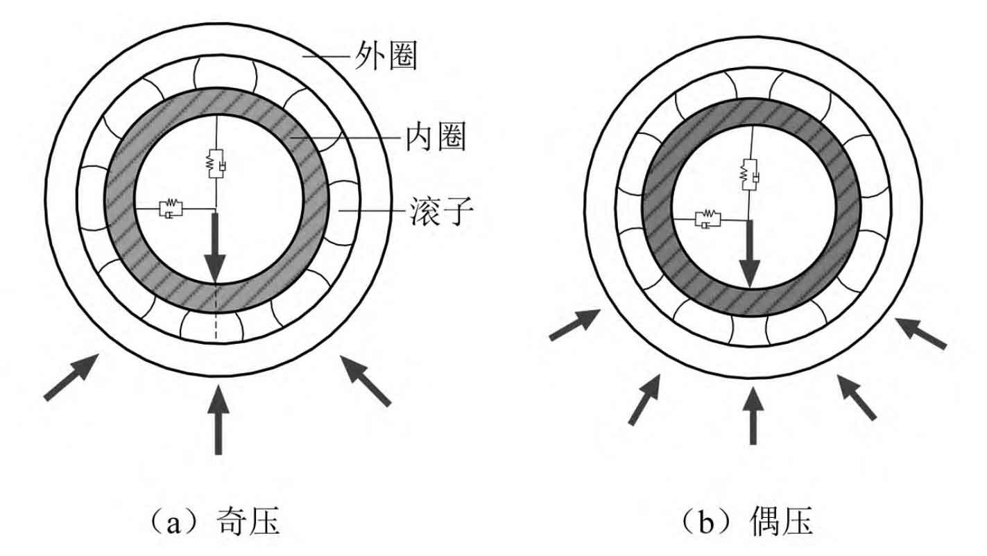

In the formula: Kx, y (t) is the time-varying meshing stiffness of the bearings in the horizontal and vertical directions; K0 is the static stiffness of the bearing, K0=(kbe+kb0)/2; Ka is the amplitude of bearing stiffness fluctuation; Fb is the passing frequency; β 0 is the initial phase angle.
1.4 Tooth side clearance
When there is clearance between the teeth, the phenomenon of disengagement will occur during the operation of spur gears with large vibration or small torque. To explore the impact of tooth disengagement on the optimization results, this paper uses a segmented function to characterize the relationship between the tooth side clearance and the relative displacement of spur gear pairs along the meshing line direction.
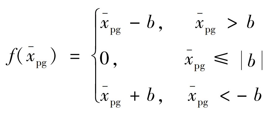
In the formula: b is the gear tooth clearance; X-pg is the relative displacement of the spur gear pair along the meshing line direction. When x-pgb, the spur gear pair is in a normal meshing state. When x-pg ≤ b, the spur gear pair is in a disengaged state.
1.5 Parameterized Dynamic Model of Fixed Axis Transmission System
According to the analysis of the dynamic model in section 1.3, any fixed axis transmission system can be assembled into a stiffness matrix according to the nodes, as shown in Figure 5. Therefore, the total stiffness matrix of any given shaft transmission system can be expressed as a function.

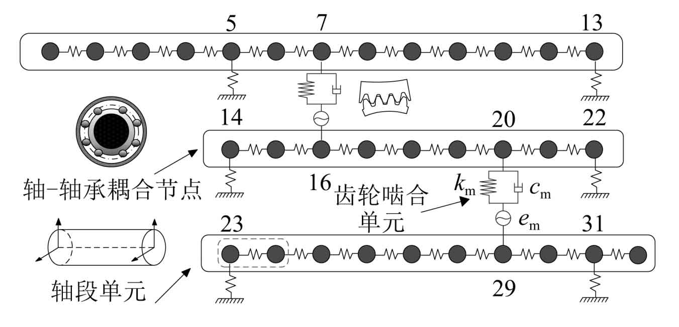
In the formula: n1 is the installation parameter of the first stage spur gear; N2 is the installation parameter for the second stage spur gear; Define the number of nodes between the installation parameters of the spur gear and the end of the intermediate shaft, n1/2=1, 2, 3,…, (n/2-1).
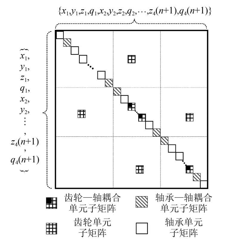
As shown in Figure 6. After applying boundary conditions and eliminating the influence of rigid body displacement, the overall stiffness matrix is obtained. The overall dynamic differential equation of the spur gear system after final assembly is:

In the formula, X represents the node displacement, and the array is {x1, y1, z1, θ 1, x2, y2, z2, θ 2,…, x4 (n+1), y4 (n+1), z4 (n+1), θ 4 (n+1)}; M. C and Kf are the mass assembly matrix, damping assembly matrix, and stiffness assembly matrix, respectively; Po is the external incentive of the system; Fe is the system error excitation. From the above analysis, it can be seen that the stiffness matrix of the overall dynamics is a function of various macroscopic parameters. Therefore, the dynamic response of the system obtained through numerical calculation is a function of the same parameters. The correctness of the modeling method used in this article has been experimentally verified in the literature, so it will not be repeated.
2. Macro parameter optimization model
In order to improve the noise characteristics and quality of large-scale mining transmission systems, the setting of objective functions and the formulation of optimization strategies, as well as the selection of optimization algorithms, have not yet formed a systematic standard. This article takes the root mean square value of the meshing force of the spur gear obtained through numerical calculation and the quality of the transmission system including the shaft system as different objective functions, and comprehensively designs an optimization model and intelligent algorithm.
2.1 Objective function
2.1.1 Objective function of coincidence degree (F1 (x))
As an important indicator that affects the load-bearing capacity and transmission stability of spur gears, the degree of overlap. In response to the dynamic characteristics of spur gear transmission systems, the greater the degree of overlap of spur gears, the smoother the transmission and the lower the vibration noise. For involute helical gears, their total overlap ε Overlay of end face overlap and axial overlap:

The calculation of end face overlap and axial overlap is as follows:

In the formula, z1/2 represents the number of teeth of the small gear and the large gear, respectively; αα T1 and αα T2 represents the end face pressure angles of the small gear and the large gear, respectively; α′ t. Is the end face meshing angle; B is the tooth width; β Is the helix angle of the helical gear; Mn is the normal modulus of helical gears. According to literature, εα Related to εβ Further deduction can be made to obtain the total meshing degree of the gear as:

The minimum opposite number of total recombinations is defined as the first objective function:

2.1.2 Optimal objective function for dynamic characteristics (F2 (x))
For mining spur gearboxes, the bearing acceleration connected to the box has a significant impact on its transmission stability and system structural noise. Therefore, the root mean square value of the bearing acceleration can be used as the optimal dynamic performance objective function, which can be written as:

In the formula, nm represents the number of pairs of meshing spur gears; Fi is the dynamic meshing force of the i-th level meshing.
2.1.3 Quality objective function (F3 (x))
The spur gear system needs to minimize volume and mass while meeting the requirements of strength and dynamic characteristics. For the secondary large-scale mining transmission system, its mass is the superposition of the shaft, spur gear, and shell mass. Since this article only considers the transmission system, the shell mass is ignored. The transmission system mass can be expressed as:

In the formula, Li represents the length of the input shaft, intermediate shaft, and output shaft.
2.2 Design variables
According to the analysis of the modeling process, various macroscopic parameters that affect the stiffness matrix of the system dynamics can be used as optimization design variables:

2.3 Constraints
2.3.1 Number of teeth constraint conditions
To avoid interference, the distance between the secondary drive driven wheel and the output shaft needs to be greater than a certain value:

In the formula: r1 is the input shaft radius Zp1/2 is the number of primary or secondary active gear teeth; Zg1/2 is the number of teeth on the first or second stage driven gear; M is the modulus; α Is the phase angle; ξ For a small quantity based on security considerations, this article takes 5mm.
2.3.2 Axis diameter strength constraint

In the formula: C is the coefficient related to the shaft material; Vs is the speed of the transmission shaft; P is the power transmitted by the axis; Di is the diameter of the i-th axis.
2.3.3 Transmission ratio constraint
The transmission ratio of the secondary transmission system is generally between 8-40. Considering that the change in the number of teeth after optimization will lead to a change in the total transmission ratio, it is necessary to constrain the total transmission ratio.
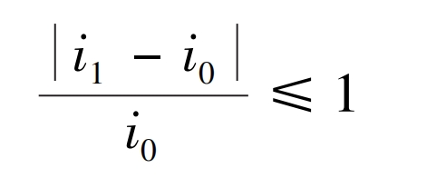
In the formula, i0 and i1 are the transmission ratios before and after optimization, respectively.
2.3.4 Strength constraint conditions
Strength constraints include the tooth surface contact fatigue strength, root bending fatigue strength, and shaft torsional strength of spur gear pairs.
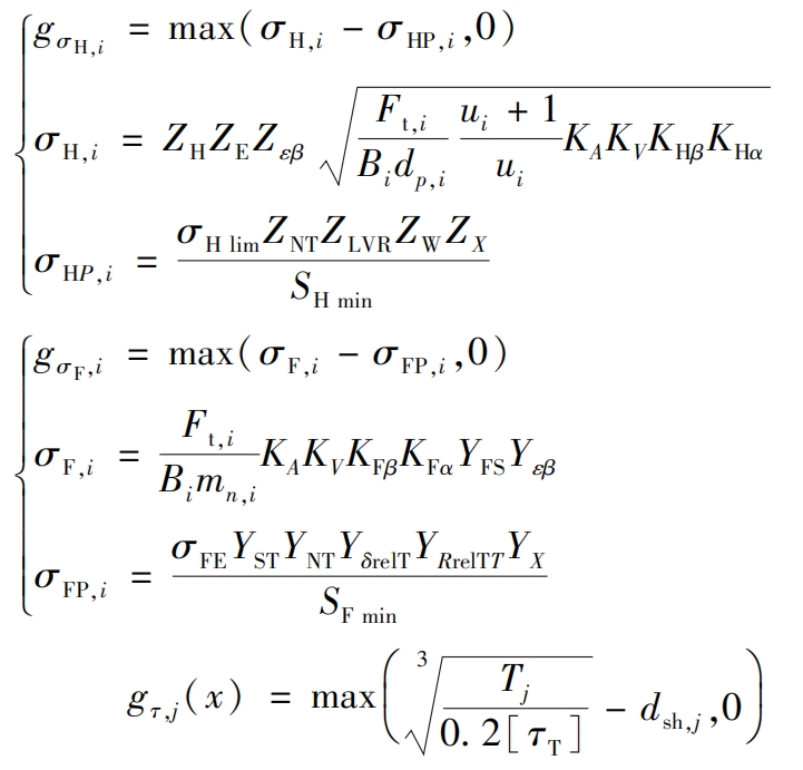
2.4 Algorithm selection
Due to the optimization problem based on Newmark ⁃ in this article β The numerical solution set obtained from real-time computation has strong nonlinearity, so gradient related optimization algorithms cannot be used for optimization. Group optimization algorithms, as a random search algorithm using populations, provide ideas for such problems. NSGA ⁃Ⅱ considers both crowding and elite strategies, using crowding comparison operators to reduce computational complexity and effectively avoid local convergence in the optimization process.
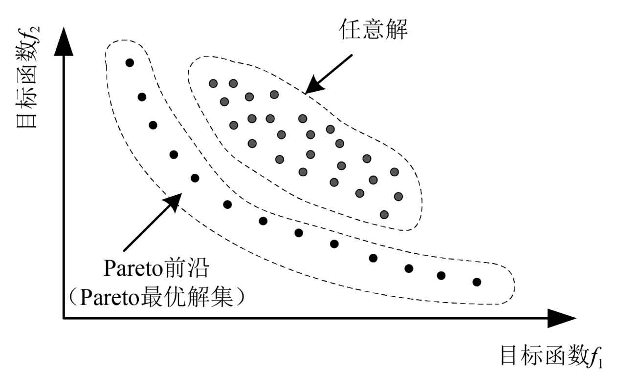
This article adopts a fast non dominated sorting genetic algorithm with elite strategy (NSGA ⁃Ⅱ) to optimize the macroscopic parameters of the entire secondary transmission system, as shown in Figure 7. Based on Pareto theory, each objective function does not need to set contribution degree, as shown in Figure 7, and the optimization result is a non inferior solution set.
The first step is to code the design variables, which depends on the number and characteristics of the optimization variables. As for this article, the design variables include integer variables such as the number of teeth and the installation position of the spur gear group, as well as floating-point variables such as shaft diameter and tooth width. Using binary encoding methods can lead to high search space dimensions, making it difficult to solve the optimal solution. Therefore, this article adopts a mixed encoding method of integer and floating-point to optimize the design variables. The specific parameter settings are shown in Table 1.
| Parameters | Numerical value |
| Population size | 10Nvar=220 |
| Cross probability | 0.5 |
| Iterations | 200 |
| Mutation probability | 0.1 |
3. Example optimization results
To verify the effectiveness of the optimization model proposed in this article, a large-scale mining spur gearbox of a certain company was taken as an example for multi-objective optimization of macroscopic parameters. For the convenience of calculation, a reducer with a rated speed of 500r/min and a load torque of 2000N · m was selected. The macroscopic parameters of the transmission system and teeth are shown in Table 2.
| Gear design | Parameter |
| 1st active gear tooth count | 21 |
| 1st driven gear tooth count | 92 |
| 2nd active gear tooth count | 26 |
| 2nd driven gear tooth count | 107 |
| First level modulus/mm | 14 |
| Secondary modulus/mm | 14 |
| First level tooth width/mm | 300 |
| Second level tooth width/mm | 170 |
| First level helix angle/(°) | 10 |
| Secondary helix angle/(°) | 14 |
| System layout | Parameter |
| Axis 1 radius/m | 0.1 |
| Axis 2 radius/m | 0.1 |
| Axis 3 radius/m | 0.1 |
| Axis length parameter n | 9 |
| First level parameter n | 12 |
| Secondary parameter n | 22 |
| Phase angle/(°) | 57 |
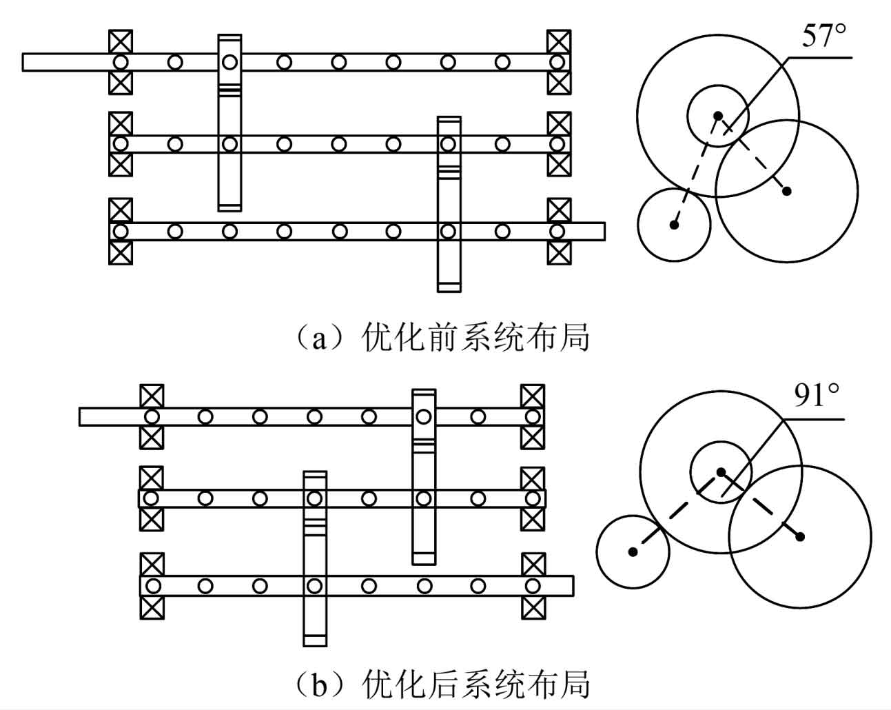
To analyze the macroscopic parameter characteristics and dynamic characteristics of multi-objective optimization results, taking the B2 optimization strategy as an example, as shown in Figure 8, it can be seen that after multi-objective optimization, the shaft layout is more compact and the machining and manufacturing are also more economical.
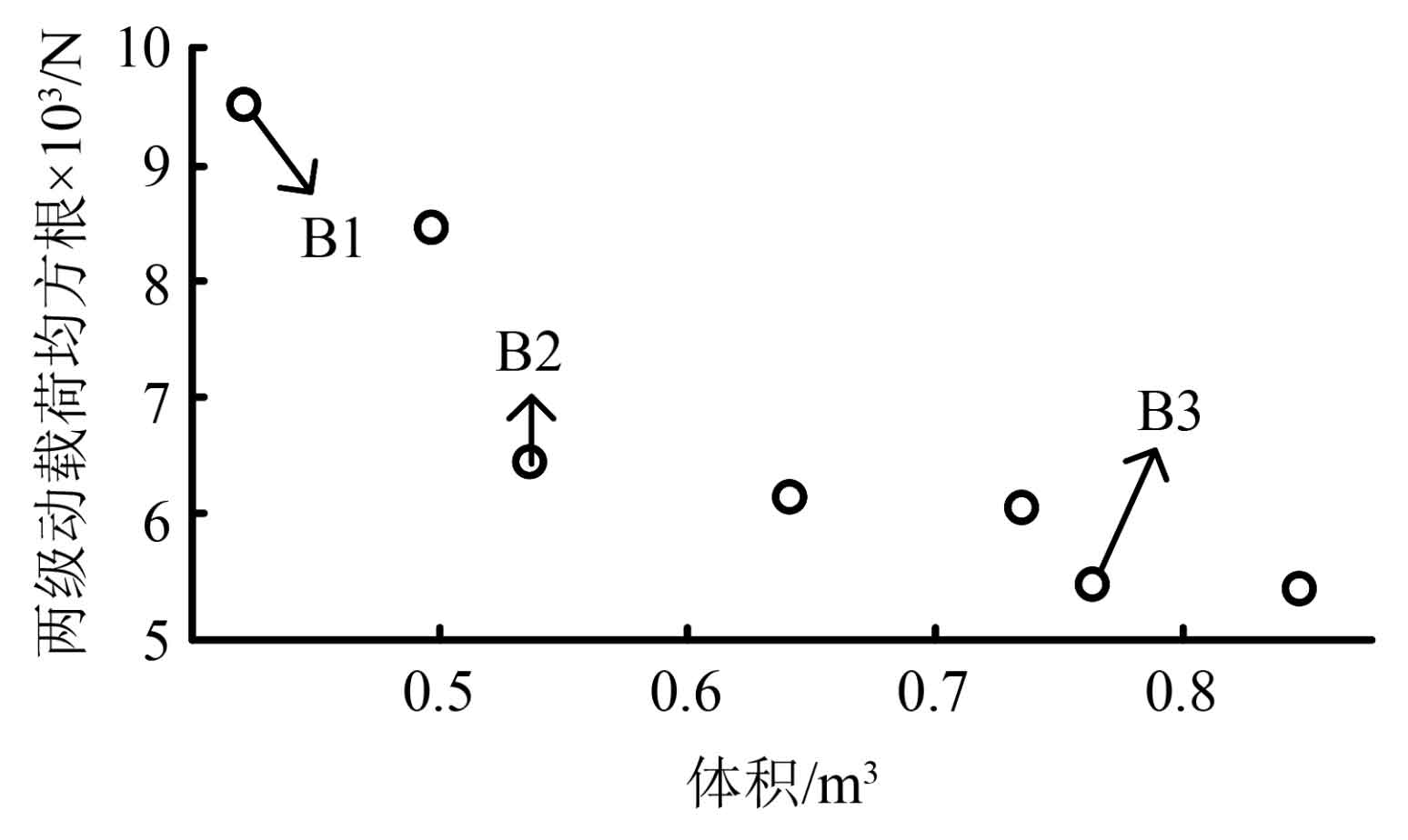
To verify the effectiveness of the optimization, the initial and optimized parameters were substituted into the MATLAB program. Firstly, the mass of the transmission system was not considered, and the objective functions of overlap and root mean square value of bearing acceleration were used for optimization. The optimization results are shown in Table A1. From the analysis of optimization results, it is found that although the root mean square value of the dynamic load of spur gears has been effectively reduced, the system mass has significantly increased. Therefore, optimization based on coincidence or bearing acceleration root mean square value is suitable for high torque, volume unrestricted designs. The volume optimization of the secondary spur gear system is an important step in the design of large-scale mining equipment. Therefore, the root mean square value of acceleration and system mass are optimized as objective functions to obtain the Pareto plane as shown in Figure 9. Within the optimized Pareto plane, three typical optimization strategies B1 to B3 are selected, as shown in Table 3, Substitute three optimization strategies to optimize parameters into the dynamic model constructed in this paper to obtain the root mean square of bearing acceleration, and compare it with the results obtained from the initial parameters, as shown in Table 4.
| Gear design | Parameter 1 | Parameter 2 | Parameter 3 | Parameter 4 |
| 1st active gear tooth count | A1:26 | B1:27 | B2:23 | B3:21 |
| 1st driven gear tooth count | 117 | 113 | 91 | 90 |
| 2nd active gear tooth count | 26 | 21 | 25 | 33 |
| 2nd driven gear tooth count | 118 | 81 | 111 | 115 |
| First level modulus/mm | 16 | 15 | 14 | 15 |
| Secondary modulus/mm | A1:16 | B1:15 | B2:12 | B3:14 |
| First level tooth width/mm | 300 | 150 | 250 | 185 |
| Second level tooth width/mm | 300 | 195 | 205 | 245 |
| First level helix angle/(°) | 23 | 13 | 20 | 20 |
| Secondary helix angle/(°) | 25 | 15 | 20 | 25 |
| System layout | Parameter 1 | Parameter 2 | Parameter 3 | Parameter 4 |
| Axis 1 radius/m | A1:0. 19 | B1:0. 24 | B2:0. 16 | B3:0. 17 |
| Axis 2 radius/m | 0. 15 | 0. 14 | 0. 13 | 0. 13 |
| Axis 3 radius/m | 0. 09 | 0. 15 | 0. 11 | 0. 07 |
| Axis length parameter n | 9 | 10 | 8 | 7 |
| First level parameter n | 9 | 10 | 8 | 7 |
| Secondary parameter n | 2 | 3 | 2 | 2 |
| Phase angle/(°) | 57 | 102 | 91 | 67 |
| Optimization strategy | Optimization objective 1/N | Optimization objective 2/m^3 |
| A1 | 7 796 | 1.15 |
| B1 | 9 469 | 0.41 |
| B2 | 6 327 | 0.53 |
| B3 | 5 283 | 0.76 |
4. Optimization parameter validation
Select the parameters of strategy B2 and substitute them into the program to obtain the time-domain response of the dynamic meshing force of the first and second stage spur gears. After Fourier transform, obtain the frequency-domain signal and compare it with the response before optimization. The meshing frequency of the first stage spur gear before optimization is:

The meshing frequency of the secondary spur gear is:

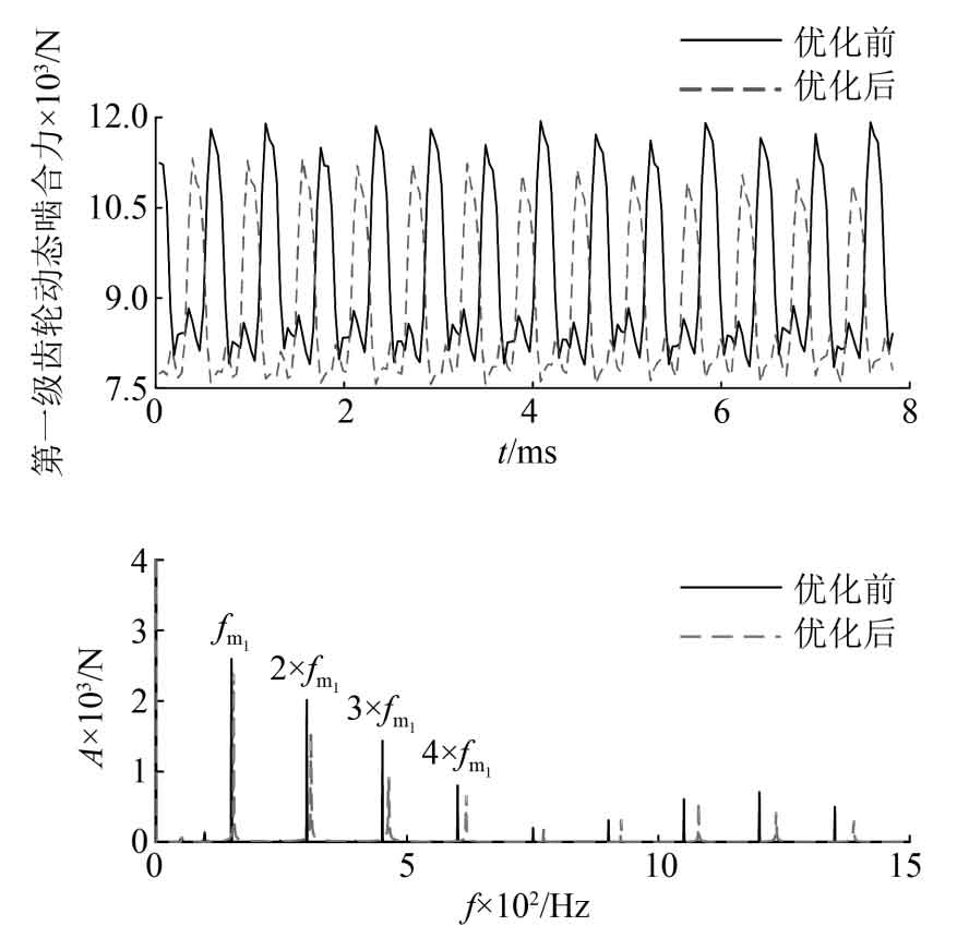
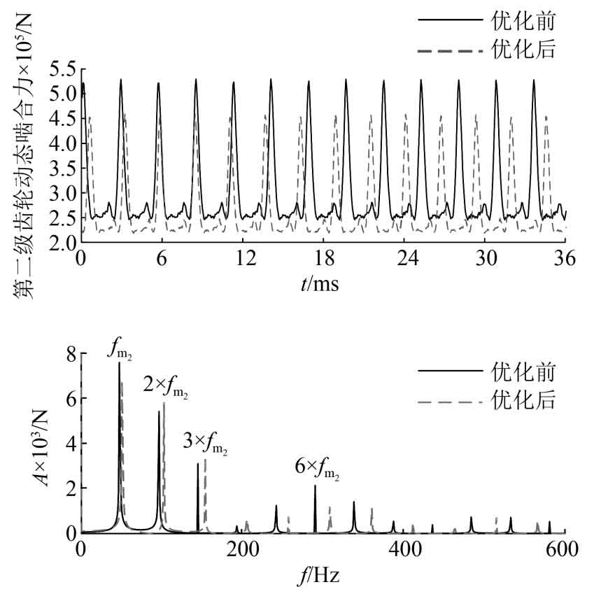
As shown in Figure 10, the amplitude of the optimized first stage spur gear meshing force is significantly reduced, specifically with an optimized amplitude of 2557N and a dynamic meshing force amplitude of 2770N before optimization, a decrease of 7.6%. From the frequency domain diagram, it can be seen that the main frequency components of the vibration response are the meshing frequency and its harmonics of the first stage spur gear. Due to the similarity of the meshing frequency of the first stage spur gear before and after optimization, the lower frequency components almost overlap, and gradually widen the gap at higher harmonics. The energy of most frequency components is relatively low. As shown in Figure 11, the amplitude of the optimized second stage spur gear meshing force decreased slightly, specifically with an optimized amplitude of 19537N and a dynamic meshing force amplitude of 23107N before optimization, a decrease of 15.7%. From the frequency domain diagram, it can be seen that the main frequency components of the vibration response are the meshing frequency and doubling frequency of the second level spur gear. There is a slight increase in the meshing frequency components of the second and third times. The reason is that this frequency is close to a certain natural frequency of the system. Therefore, when there is a requirement for a certain frequency component in the design, the refinement design at the frequency domain level can be achieved by changing the optimization objective function.
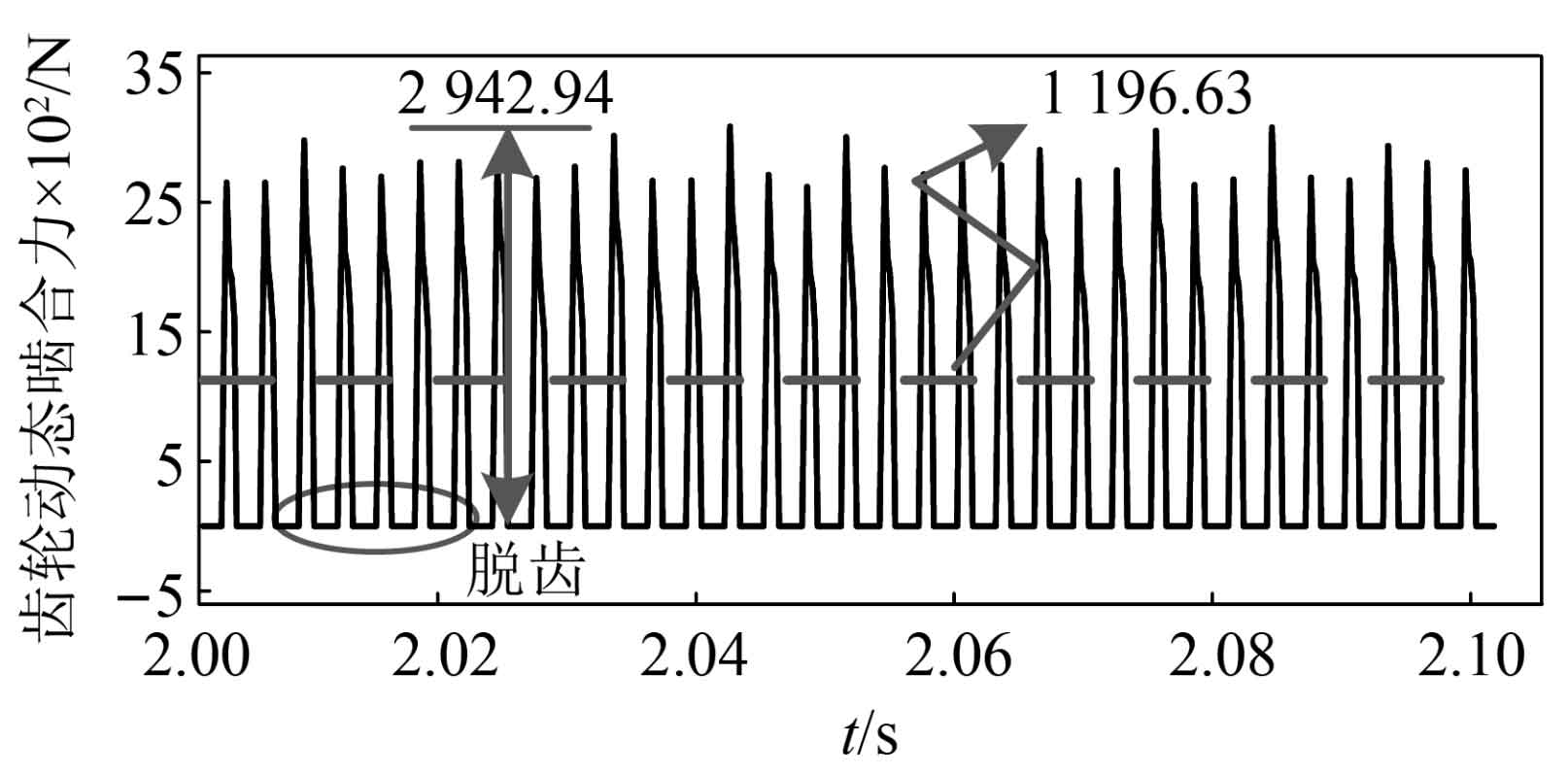
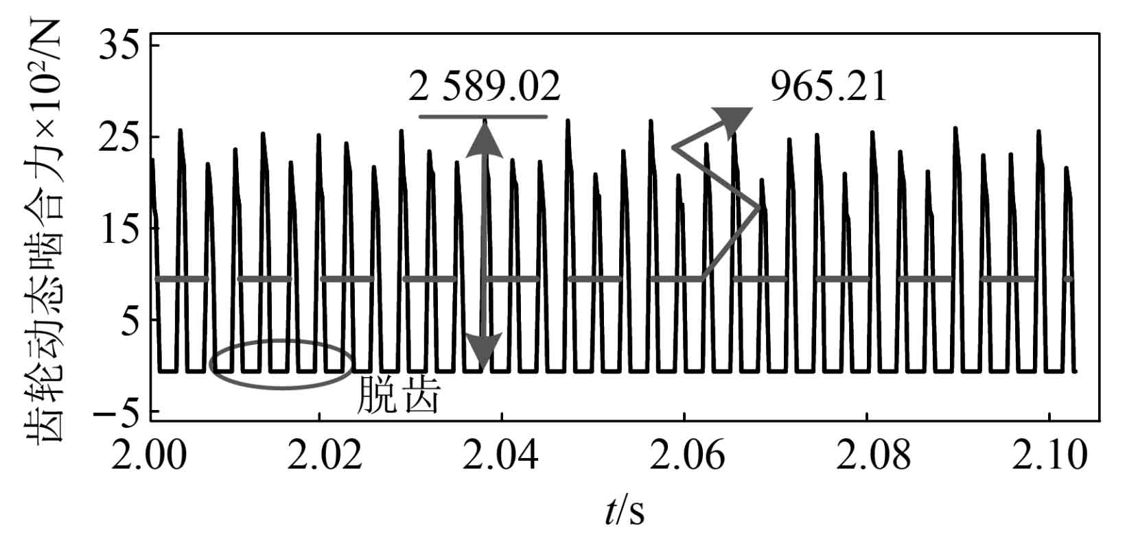
By substituting the optimization results considering eccentricity into the dynamic program, the dynamic meshing forces of the spur gear before and after optimization are obtained, as shown in Figures 12 and 13. When eccentricity is considered, the teeth will experience tooth detachment behavior, and the entire meshing process goes through a repeated process of contact, separation, and re contact. As shown in the figure, the amplitude of the dynamic meshing force of the spur gear before optimization is 2942.94N, After optimization, the amplitude decreased to 2589.02N, a decrease of 12%. It can be seen that the method proposed in this paper takes the processed real-time calculated dataset as the objective function and is suitable for spur gear transmission systems considering multi-source time-varying excitation. In addition, the average dynamic meshing force of the spur gear before optimization was 1196.63N, and after optimization it was 965.21N. The reason for the change in the average meshing force was that after optimization, the number of teeth of the spur gear changed, resulting in a change in the static balance force. In practical applications, gear matching design should be based on the strength of each level of spur gear to avoid reducing the fatigue life of spur gears.
5. Conclusion
(1) A parameterized dynamic model of a large-scale mining spur gear transmission system was established using the finite element method. The dynamic equations were solved using the Newmark time-domain integration method to obtain a numerical solution set, which reflects the mapping between design parameters, layout parameters, and dynamic response. Based on this, an optimization model was established that considers both design and layout parameters.
(2) The comparison of dynamic numerical calculation results between the optimized model and the original model shows that the NSGA ⁃ II algorithm is very effective in optimizing the dynamic performance of large-scale mining spur gear transmission systems. After multi-objective optimization, the dynamic meshing forces of the two-stage spur gears are reduced by 7.6% and 15.7%, respectively, and the volume is reduced by 27.0%.
(3) For large-scale mining spur gear transmission systems, due to the significant impact of the volume and structure of the spur gear box on its performance, multi-objective optimization results are more suitable for the design of mining transmission systems.
