
Shield tunneling machines are playing an increasingly important role in underground engineering construction. As the core component of shield tunneling machines, the reducer’s operating status directly affects the performance and safety of the machine. As one of the important components of a reducer, the wear status of multi-stage planetary gear has a significant impact on the performance and lifespan of the reducer. Detecting the wear status of the multi-stage planetary gear in the shield machine reducer is of great significance for ensuring the normal operation of the shield machine and improving the safety and efficiency of underground engineering construction.
There are two traditional methods for detecting the wear status of planetary gear: one is to evaluate the operating status of the equipment by monitoring the oil index of the fan gear, and the other is to use an improved spectral residual based detection method for the meshing wear status of spur cylindrical gears. The above methods are time-consuming and laborious, making it difficult to achieve real-time detection. To solve the above problems, this article proposes a multi-stage planetary gear wear detection method for shield machine reducers, which can real-time detect the wear status of planetary gear, improve the safety and efficiency of shield machine operation.
1. Design of wear detection for multi-stage planetary gear in a reducer
1.1 Noise reduction of vibration signals of multi-stage planetary gear in reducers
1.1.1 Necessity of taking noise reduction measures
In planetary gear, the collection and processing of vibration signals are crucial, as these signals contain important information about the operating status of the equipment. However, these signals are often affected by environmental noise and electromagnetic interference inside the equipment, resulting in a large amount of noise in the signal [3]. The presence of these noises affects the overall stability of the signal, further affecting the accuracy of wear state detection.
To solve this problem, effective noise reduction measures need to be taken to process the collected vibration signals. Among them, the translation invariant wavelet denoising method is a widely used denoising technique.
1.1.2 Translation Invariant Wavelet Denoising Principle
This method utilizes the characteristics of wavelet transform to perform multi-scale analysis on signals, thereby separating noise and useful signals. This method can effectively remove noise from the signal, improve the stability of the signal, and further improve the accuracy of wear state detection.
Assuming the sampled discrete data is X H, obtain the corresponding orthogonal wavelet transform method and obtain the orthogonal wavelet transform decomposition formula for the vibration signal of the planetary gearbox:
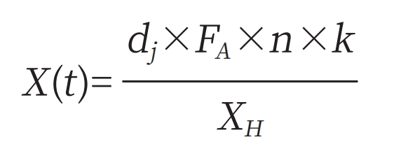
In the formula: dj represents the scale coefficient; FA represents wavelet coefficients; N represents the number of filtering processes; K represents a constant.
From the perspective of signal filtering, orthogonal wavelet decomposition is an effective signal processing method. In the process of orthogonal wavelet decomposition, discrete signals are processed through a series of high pass and low-pass filters to extract high-frequency and low-frequency information from the signal.
This processing method can effectively filter out noise and other interfering components in the signal, retain useful information in the signal, and provide an important foundation for subsequent signal analysis and processing. Orthogonal wavelet decomposition plays an important role in signal filtering, which can improve the clarity and comprehensibility of signals and provide strong technical support for various application fields.
The signal reconstruction process DFG can be expressed in the form of formula (2):
In the formula: λ Indicates the number of layers of wavelet decomposition.
1.1.3 Noise reduction steps
The noise contaminated signal will be restored to the original signal, and the corresponding noise reduction steps for the multi-stage planetary gear vibration signal of the reducer are as follows.
Step 1: Use the collected planetary gear vibration signal as input.
Step 2: Using orthogonal wavelet transform technology, the noisy signal is processed. Through wavelet decomposition, the noisy signal is decomposed into multiple sub signals, each corresponding to a set of wavelet coefficients. These coefficients contain noise components and important signal features.
Step 3: Perform multiple cyclic translation processing on the vibration signal of the planetary gear. The corresponding calculation formula is:
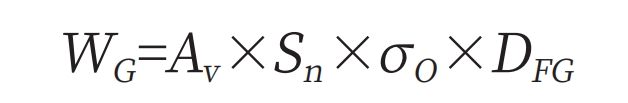
In the formula: WG represents the result of multiple cycle translation processing; Av represents the translation loop operator; Sn represents the root of the square difference; σ O represents the soft threshold.
Step 4: Use the soft threshold denoising method in the translation invariant denoising method to denoise the signal. The corresponding soft threshold function can be expressed in the form of formula (4):
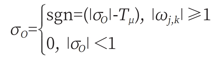
In the formula: T μ Represents temporal dimension characteristics.
Step 5: Translate the vibration signal in the opposite direction again and calculate the average value of the processing results.
Step 6: Output the multi-stage planetary gear vibration signal of the reducer to reduce noise.
1.2 Segmenting the meshing area of planetary gear images
1.2.1 Selection of Grid Region Segmentation Methods
When the planetary gear region is located at the edge of the grid region, applying threshold methods can result in incomplete segmentation of the grid region. The regional positions of planetary gear have different heights, and the wear areas of planetary gear at different heights show different values in the image. This article adopts a grid region segmentation method that combines region segmentation, region aggregation, and edge correction.
The use of region segmentation methods can avoid detecting low grayscale grid areas. The large area aggregation algorithm identifies the grid regions in the candidate grid regions and combines them as a whole to obtain the grid regions. Based on the terrain characteristics of the original grid area, adjust the boundaries of the original grid area. It overcomes the incomplete partitioning problem caused by pitting on the boundary of the original grid area, and thus obtains the final partitioning result of the original grid area.
1.2.2 Adaptive Local Threshold Calculation
The grayscale characteristics of the worn parts of each small gear are different, so it is not suitable to use global cutting technology. The boundary of the modified grid area usually includes some background areas with lower grayscale values, which have similar pitting grayscale features.
ZHY Gear uses adaptive local threshold segmentation to obtain candidate regions and removes false positive regions from them based on shape features. The expression for adaptive local threshold is as follows:
In the formula, A1 and A2 respectively represent the expectations of the source domain and the target domain; S F represents the feature mapping of tensor product in the space of multi-stage planetary gear in shield machine reducers.
1.2.3 Obtaining Grid Area Candidates
In order to reduce the segmentation error of the grid area, based on the segmentation results of the class grid area, this section is segmented to obtain the candidate items of the grid area and determine whether the segmentation results of the upper and lower regions are correct. If the regional segmentation result is incorrect, improvement is needed.
1.2.4 Determine whether the division of class grid regions is correct
In similar planetary gear types, different tooth surfaces have the same height. The height of the grid area on the surface of different planetary gear is basically the same. Assuming the coefficient threshold is Thi, the high H-degree of the segmentation result of the Hei grid division region can be used to determine whether the segmentation of the class grid division region is correct. The specific formula is:
When formula (6) holds, it can be determined that the region segmentation is incorrect.
1.2.5 Obtain planetary gear image meshing area
The coefficient threshold Thi is determined by the height of the meshing zone of the planetary gear. Considering that there may be some surface images of the planetary gear, the value of Thi may be smaller than the width of the meshing zone. To obtain the meshing area of the planetary gear image through formula (7):
In the formula: η The time-frequency spectrum representing the signal; γ Represents an FM signal.
According to the above formula, map the depth characteristics of vibration signals in the source and target domains to the space of multi-stage planetary gear in the shield machine reducer. In the new feature space, determine the error between the actual classification and recognition results of vibration signals and the expected results, and fine tune the network parameters of the target to minimize the error. Finally, by fine-tuning the parameters, the vibration signal samples of the multi-stage planetary gear of the input shield machine reducer are classified and recognized, and the meshing area of the planetary gear image is segmented.
1.3 Detection of pitting areas
Thresholds with different depths have different call proportion values. Firstly, adaptive local branch segmentation is used to obtain candidate branch regions, and then the pseudo candidate regions in the candidate regions are represented by formal functions.
Pulse excitation is a transitional excitation method, in theory, the pulse function is continuous and constant within an infinite frequency range, and energy is mainly concentrated in the frequency based range.
| Name | Model | Performance |
| Computer | IBM | |
| Multi-channel data acquisition system | LMS-SC305 | 16 channels |
| Data analysis system | LMS Test Lab Modal | Analysis Template |
| Signal conditioner | B&K Type 2692 | 4-channel |
| Accelerometer | B&K 4326A-001 | Sensitivity 3 ± 15% PC/g |
| Pulse hammer | B&K 8202 | Sensitivity 3.97pC/N |
First read in the data stream, then process the threshold, and finally perform detection. The main instruments and equipment required for testing are shown in Table 1. In order to determine the main properties of the reducer box, the experiment used the boundary requirement of free support to complete the detection.
2. Comparative experiments
2.1 Experimental Description
The wear status detection method for multi-stage planetary gear in the shield machine reducer mentioned in the article is used as the experimental group. The equipment operation status detection method is evaluated by monitoring the gear oil index of the fan. Based on the improved spectral residual, the wear status detection method for spur gear meshing is used as the control group A and control group B, respectively. The three methods are compared.
2.2 Experimental preparation
Multiple point excitation and single point pickup pulse excitation method were selected for signal acquisition in the experiment to obtain data. The relevant parameters of the planetary gearbox are shown in Table 2. Set the frequency of the experimental signal collection to 11500H z, the sampling time to 15s, and the spindle speed of the planetary gearbox to 19r/min.
| Parameters | Index |
| Module/mm | 2.25/2.15/1.75 |
| Number of teeth | 21/19/16 |
| Tooth width/mm | 13/14/16 |
| Tooth top height coefficient | 1.0 |
| Top clearance coefficient | 0.25 |
| Top stand angle/º | 20 |
| Gear surface machining accuracy | Level 8 |
2.3 Test results
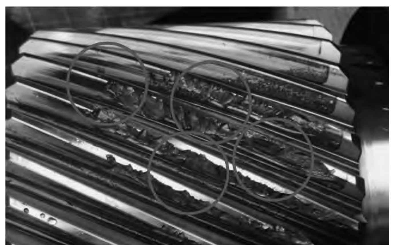
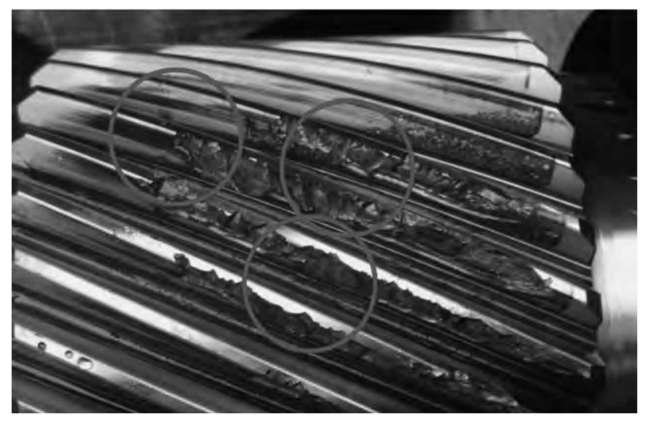
The original planetary gear wear image is shown in Figure 1. The wear image detection results of the method in the article are shown in Figure 2. The detection results of method A in control group are shown in Figure 3. The detection results of method B in control group are shown in Figure 4.
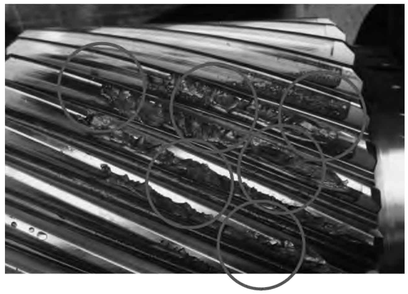
From Figures 1, 2, 3, and 4, it can be seen that the results of the method used in this paper for detecting planetary gear wear are the same as the original wear position of the planetary gear, but the control group A method and the control group B method cannot detect all positions of planetary gear wear. From this, it can be seen that the method proposed in this article can accurately detect the wear status of planetary gear, and the detection effect of planetary gear wear status is good.
Set the number of iterations to 500, and compare the detection accuracy test results of different methods using the control group A method, control group B method, and our method, as shown in Figure 5.
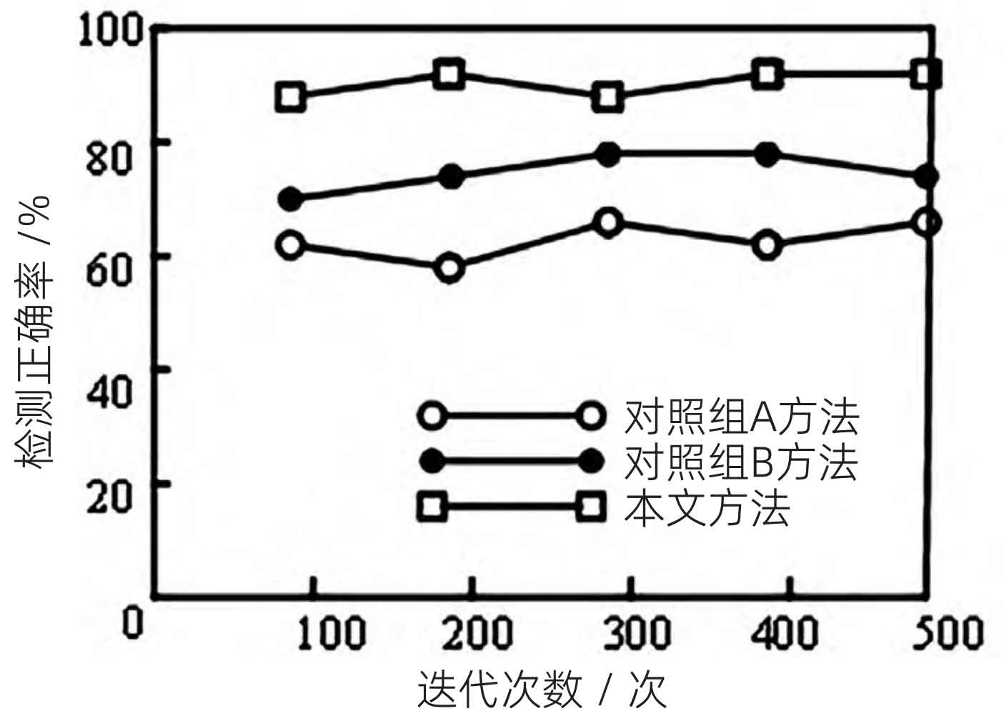
From Figure 5, it can be seen that during 500 iterations, the average accuracy rate of planetary gear wear state detection in our method can reach about 90%, while the average accuracy rate of planetary gear mesh wear state detection in control group A and control group B methods is about 70%, both lower than our method. From this, it can be seen that the accuracy of the planetary gear wear state detected by the method in this article is higher than that of the control group A method and the control group B method.
3. Conclusion
The operation status of planetary gear is directly related to the working quality of shield machine reducers. In order to ensure their normal operation, it is necessary to regularly inspect the wear status of multi-stage planetary gear in shield machine reducers. This article introduces an analysis method for the wear condition of multi-stage planetary gear in shield machine reducers. The application of this measurement method can greatly improve the accuracy of measuring the wear condition of multi-stage planetary gear, far exceeding the methods of control group A and control group B. After comparative analysis, it is shown that there is good consistency between the results and experimental data, and the time deviation between the two is relatively small. The similarity in vibration mode design jointly proves the effectiveness of basic research and experimental techniques.