
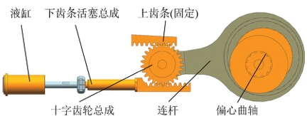
The structural principle of the long-stroke reciprocating pump with a gear-rack combined crank-connecting rod mechanism is shown in Figure 1. The structural principle is to replace the crosshead structure in traditional reciprocating pumps with a symmetrically arranged pair of gears (hereinafter referred to as cross gears) and a gear-rack mechanism with bilateral meshing. The upper rack is fixed to the frame, and the lower rack is connected to the piston rod to drive the piston to reciprocate within the hydraulic cylinder. During the rotation of the crank from the right dead center to the left dead center, the crank-connecting rod pushes the gear forward, while the fixed upper rack drives the gear to rotate, resulting in a displacement distance of the lower rack that is the sum of the displacement SC of the gear’s center of rotation and the length of the pitch circle SJ of the gear during its rotation from the left dead center to the right dead center. With a constant eccentricity of the crankshaft, the stroke is increased.
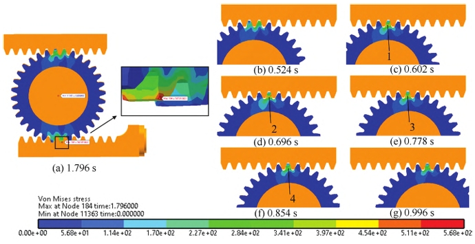
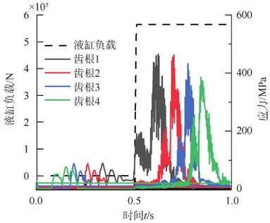
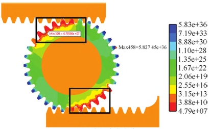
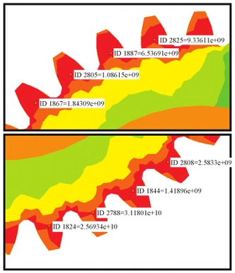
The fatigue life of gears is closely related to the performance of their materials. For low-speed heavy-duty conditions, if the service life of the cross gear can reach more than 10,000 hours, it can be considered that the gear can meet the fatigue life requirements. The material used for the cross gear is 20Cr2Ni4A steel, and the heat treatment process is carburizing and quenching followed by low-temperature tempering.Gear The minimum fatigue life of the gear is 13316.28 hours, which meets the fatigue life requirements. The fatigue life of the eight main load-bearing tooth roots has reached more than 277777 hours, far exceeding the design life, indicating that the failure mode of the cross gear is likely to first occur from the sides of the gear transition, eventually leading to the fracture of the entire tooth. The fatigue life of the gear can be extended by modifying the root transition curve to reduce stress concentration or increasing tooth width. The root stress during gear meshing is only about 100 MPa; the 0.5-1 second is the drainage process, Gear and the load on the hydraulic cylinder increases to 5.7×10⁵ PaN, tooth root 1 first engages with the upper rack, and the tooth root stress during the engagement reaches about 450 MPa; when tooth root 1 engages, the piston speed accelerates from 0, and the acceleration is at its peak. When tooth roots 2 and 3 engage with the gear, the piston speed reaches its maximum value, and the acceleration is 0. When tooth root 4 engages, the acceleration reverses and the piston begins to decelerate. Due to the effect of inertia force, the tooth root stress during the engagement of tooth roots 2, 3, and 4 exhibits a decreasing characteristic, and the tooth root stress during the engagement of tooth root 4 is only 399.4 MPa.
(1) A new range-extending mechanism driven by a gear and rack is proposed in this paper, Gear replacing the traditional crosshead structure. With the same eccentricity of the crankshaft, the displacement stroke is doubled, and the peak speed of the piston is comparable to that of traditional reciprocating pumps at the same power. The peak acceleration is only 1/2 of that of traditional reciprocating pumps.
(2) Analyzing the flow characteristics of the new reciprocating pump, its flow pulsation rate is comparable to that of traditional reciprocating pumps, Gear and the fluctuation frequency of flow per unit time is only 1/2 of that of traditional reciprocating pumps, greatly reducing the number of piston reversals and pump valve switching frequencies, effectively extending the service life of vulnerable parts such as pistons and pump valves.
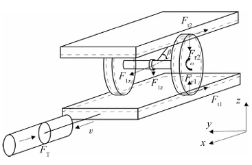
(3) Conduct a force analysis on the cross gear in the gear-rack range-extending mechanism, and perform dynamic simulations on the new three-cylinder reciprocating pump to obtain the transient dynamic stress of the cross gear.
(4) The fatigue life curve of the gear was fitted, and the fatigue analysis of the cross gear was conducted. The results showed that the minimum fatigue life of the gear was 13,316.28 hours, which met the design requirements. The weak points of the gear’s fatigue strength were identified, and suggestions for improving the gear structure were proposed, which can provide theoretical support for subsequent development.