
Abstract
To obtain the steady-state temperature field and thermal deformation field of electric drive transmission helical gear, the average friction heat flux density on the meshing surface and the convection heat transfer coefficients on other surfaces of the helical gear is derived based on the meshing principle of helical gear and theories of heat transfer and tribology. A parametric thermal analysis model of the helical gear is established using the APDL language, which allows the acquisition of the steady-state temperature field and thermal deformation field of the helical gear. The influence laws of different gear models on the steady-state temperature field and thermal deformation field are revealed. The research results show that the steady-state temperature field varies in a gradient, with the highest temperature on the meshing surface and the lowest on the hub. Two distinct high-temperature regions exist on the meshing surface, located within the two double-tooth meshing areas. In the direction of tooth height, the tooth surface temperature exhibits an “M”-shaped distribution. The maximum temperature in the double-tooth meshing area at the meshing-in end is close to the tooth root, while that at the meshing-out end is close to the tooth tip. In the direction of tooth width, the tooth surface temperature is asymmetrically distributed. For a clockwise rotating right-hand helical gear, the high-temperature zone in the double-tooth meshing area at the meshing-in end is close to the front face of the gear, while that at the meshing-out end is close to the rear face. Due to accumulated deformation, the overall thermal deformation of the helical gear is maximum at the tooth tip and minimum at the hub, with the maximum deformation occurring near the two end faces of the gear. When considering the deformation along the meshing line direction, the thermal deformation at the rear face is greater than that at the front face, consistent with the temperature distribution along the tooth width. To save computational cost, a single-tooth model can be used to replace the full-tooth model with high accuracy when calculating the steady-state temperature field, but only the full-tooth model is accurate for calculating the thermal deformation field, with other models exhibiting significant errors.
1. Introduction
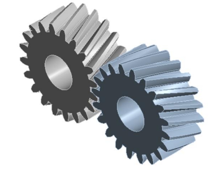
Helical gear exhibit excellent transmission performance and load-bearing capacity, making them widely used in electric drive transmission systems. However, during the transmission process of helical gear, sliding friction occurs in both the axial and radial directions between the meshing tooth surfaces. Under high-speed and heavy-load conditions, significant heat is generated, leading to potential issues such as scuffing failure and thermal deformation of the gears. Thermal deformation alters the involute tooth profile of the gears, affecting their transmission meshing characteristics and causing vibrations and noise. For electric drive transmission gears, the higher the rotational speed, the more heat generated during gear transmission. Therefore, studying the temperature field and thermal deformation field of electric drive transmission helical gear is of great significance.
Currently, the primary methods for studying the temperature field and thermal deformation field of gears include numerical calculation methods , experimental analysis methods , and finite element methods . Li Guihua et al. proposed an approximate method for calculating the temperature field of meshing gears based on mechanical drawing principles and heat conduction theory. By utilizing the Saint-Venant principle for corrections, their results were found to be very close to those obtained using the finite element method. Sutter et al. introduced an experimental method for measuring the flash temperature on sliding surfaces, employing an enhanced CCD camera and visible light thermometry to measure the temperature field on the sliding surfaces. Guo Heng et al. established a finite element analysis model for the gear temperature field and transmission error using Workbench, and explored the effects of changes in rotational speed and torque on the gear temperature as well as the influence of changes in rotational speed and temperature on the gear transmission error. Li Wei et al. derived formulas for calculating the friction heat flux density and convection heat transfer coefficients of gears, and used the APDL language to create a single-tooth parametric model of spur gears. They obtained the single-tooth temperature field of the spur gears and analyzed the influence of different parameters on the gear temperature. Xue Jianhua et al. analyzed the meshing surface of helical gear to determine the distribution laws of contact lines, loads, and friction heat flux. Considering the influence of temperature, they established the bulk temperature field of helical gear and conducted thermomechanical coupling analysis.
In summary, most finite element analyses of the temperature field and thermal deformation field of helical gear utilize the Workbench or APDL language to establish finite element analysis models of the gears, studying the effects of key factors such as rotational speed, load, and material on the results. However, regarding the impact of the model itself on the accuracy of the analysis results, no relevant literature has been published to date. In this paper, the APDL language is utilized to establish a parametric model of helical gear, with the aim of investigating the influence of different models, such as partial-tooth and full-tooth models, on the calculation accuracy of the steady-state temperature field and thermal deformation field.
2. Heat Balance Equation and Boundary Conditions of Helical Gear
During the meshing process of helical gear, friction between the two contacting meshing surfaces generates heat. Part of this heat is transmitted into the gear body, while the other part is dissipated through convection heat transfer between the various gear surfaces and the lubricating oil. After operating for a period, the gear transmission system reaches a thermal equilibrium state, at which point the bulk temperature field of the helical gear is a steady-state temperature field. The heat conduction differential equation for the steady-state temperature field of the gear transmission system is derived based on the law of conservation of energy and Fourier’s law of heat conduction, as shown in Equation (1).
lambda(∂x2∂2t+∂y2∂2t+∂z2∂2t)=0(1)
where λ is the thermal conductivity and t is the temperature.
To solve for the steady-state temperature field of the gear, it is necessary to first determine the boundary conditions on its various surfaces. A schematic diagram of the gear surfaces .
The boundary conditions on the various gear surfaces can be obtained using Newton’s cooling formula and Fourier’s law. Specifically, the meshing surface represents a combination of the second and third types of boundary conditions (S and T), as shown in Equation (2), while the non-meshing surfaces, tooth tips, two side tooth roots, and end faces represent the third type of boundary condition (T), as shown in Equation (3).
−λ(∂n∂t)=s1(tc−to)−qw(2)
−λ(∂n∂t)=s2(tc−to)(3)
where n is the normal vector of the heat transfer surface, s1 is the convection heat transfer coefficient on the meshing surface, s2 is the convection heat transfer coefficient on the tooth tip, non-meshing surfaces, end faces, and two side tooth roots, tc and to are the initial temperatures of the gear surfaces and lubricating oil, respectively, and qw is the average friction heat flux density.
3. Average Friction Heat Flux Density and Convection Heat Transfer Coefficients
3.1 Dimensionless Coordinates
To represent the position of any meshing point on the gear meshing line, this paper introduces the dimensionless coordinate Γ. schematic diagram of the dimensionless coordinates on the meshing line of external meshing gears.
In this diagram, NI represents the theoretical meshing-in point, NA represents the actual meshing-in point, NB and ND are the boundaries between the single-tooth and double-tooth meshing areas, NC is the node, NE is the actual meshing-out point, and NO is the theoretical meshing-out point. Taking the meshing line as the coordinate axis, the dimensionless coordinate Γ of any point NK on the meshing line is defined as the ratio of the distance from this point to the node NC to the length of the segment NINC, with the positive direction specified from point NI to point NO. The calculation formula for the dimensionless coordinate Γ of point NK can be derived from the geometric relationship, as given in Equation (4).
Gamma=rb1tanαncrb1tanαnk−rb1tanαnc=tanαnctanαnk−1(4)
where αnc is the pressure angle at the pitch circle, and αnk is the pressure angle of the driving gear corresponding to the meshing point NK.
3.2 Average Friction Heat Flux Density
To solve for the steady-state temperature field of the helical gear, the average friction heat flux density must be applied to the meshing surface. The value of the average friction heat flux density is determined by Equation (5) [16].
q∗=2T1πkfμPMfτ0(v1−v2)(5)
where kf is the tooth-to-tooth distribution coefficient of the friction heat flux density, μ is the friction coefficient, PM is the maximum Hertz contact pressure, f is the thermal energy conversion coefficient (taken as 0.95 in this paper), T1 is the meshing period of the driving gear, τ0 is the half-bandwidth of the time-domain contact, v1 and v2 are the tangential velocities of the meshing points on the driving and driven gears, respectively, determined by Equation (6).
tau0=v1b0,b0=πEPM8wR=2πRv1wE,v1=30R1πn1,v2=30R2πn2(6)
where E is the equivalent elastic modulus, R is the combined curvature radius, w is the unit line load, determined by Equations (7) and (8).
w=Lrb1n1cosβb9549PηK(7)
R=R1+R2R1R2,E1=E11−u12+E21−u22(8)
where P is the input power, η is the transmission efficiency, L is the contact line length, βb is the helix angle at the base circle, R1 and R2 are the curvature radii of the driving and driven gears, respectively, u1 and u2 are the Poisson’s ratios of the driving and driven gears, respectively, and E1 and E2 are the elastic moduli of the driving and driven gears, respectively.
3.3 Convection Heat Transfer Coefficients
(1) Convection Heat Transfer Coefficient on Tooth Tips
The convection heat transfer coefficient on tooth tips is determined by Equation (9).
hd=0.664λoPo0.333(νoω)0.5(9)
where λo is the thermal conductivity of the lubricating oil, Po is the Prandtl number of the lubricating oil (Po=ρocoνo/λo, where ρo is the density of the lubricating oil, co is the specific heat capacity of the lubricating oil, and νo is the kinematic viscosity of the lubricating oil), and ω is the angular velocity of the gear.
(2) Convection Heat Transfer Coefficient on Tooth Surfaces and Tooth Root Transition Surfaces
The convection heat transfer coefficient on tooth surfaces and tooth root transition surfaces is determined by Equation (10).
ha=0.228Re0.731Po0.333Ldλo(10)
where Ld is the pitch circle radius of the driving gear, and Re is the Reynolds number of the lubricating oil, determined by Equation (11).
Re=νoωrnk2(11)
where rnk is the radius of any meshing point on the gear.
(3) Convection Heat Transfer Coefficient on End Faces
The convection heat transfer on end faces is similar to that on rotating disks, and can be divided into laminar, transition, and turbulent flow regimes depending on the Reynolds number. The convection heat transfer coefficients for these three regimes are given by Equation (12).
ht=0.308λmix(mz+2)0.5×Pmix0.5(νmixω)0.5,Re≤2×10⁵
ht=10−19λmix(νmixω)4rnk7,2×105≤Re≤2.5×10⁵
ht=0.0197λmix(mz+2.6)0.2×(νmixω)0.8rnk0.6,Re≥2.5×10⁵(12)
where mz has a value of 2, Pmix is the Prandtl number of the oil-air mixture, νmix is the kinematic viscosity of the oil-air mixture, and λmix is the thermal conductivity of the oil-air mixture. The characteristic parameters of the oil-air mixture can be constructed by linearly combining the characteristic parameters of the oil and air media in proportion to αmix, as shown in Equation (13).
numix,λmix,Pmix=νa,λa,Pa×(1−αmix)+νo,λo,Po×αmix(13)
where νa, λa, and Pa are the viscosity coefficient, thermal conductivity, and Prandtl number of air, respectively, and d is the correction coefficient for the influence of actual operating conditions on mixed flow, determined by d=rnk/ra, where ra is the radius of the tooth tip circle.
4. Finite Element Parametric Model
The parameters of the helical gear and lubricating oil are listed in Tables 1 and 2, respectively.
Table 1. Parameters of the Helical Gear
| Parameter | Value | Parameter | Value |
|---|---|---|---|
| Driving gear speed n1 (rpm) | 2000 | Elastic modulus E (GPa) | 206 |
| Number of teeth z1, z2 | 23, 30 | Poisson’s ratio ν | 0.3 |
| Module m (mm) | 3 | Specific heat capacity c (J/kg·K) | 465 |
| Pressure angle α (°) | 20 | Thermal conductivity λ (W/m·K) | 46 |
| Tooth width b (mm) | 20 | Thermal expansion coefficient k (10−5/∘C) | 11.3 |
| Helix angle β (°) | 8 | Density ρ (kg/m³) | 7850 |
| Input power P (kW) | 50 |
Table 2. Parameters of the Lubricating Oil
| Parameter | Value |
|---|---|
| Lubricating Oil Type | SCH632 |
| Density (ρo) | 870 kg/m³ |
| Kinematic Viscosity (υo) | 320 cSt at 40°C, 38.5 cSt at 100°C |
| Thermal Conductivity (λo) | 2000 W/(m·K) |
| Specific Heat Capacity (co) | 0.14 J/(kg·K) |
These parameters describe the physical and thermal properties of the lubricating oil used in the study, which is essential for calculating the convective heat transfer coefficient and understanding the heat transfer behavior within the gear system.