This article focuses on the dynamic optimization of macro parameters in large mining gear transmission systems. It begins with an introduction to the importance of such optimization in the context of large and complex mining equipment. The core of the discussion lies in the establishment of a parameterized dynamic model and an optimization model. Through detailed analysis and case studies, the effectiveness of the proposed methods is demonstrated, and conclusions are drawn regarding the significance and future directions of this research area.
1. Introduction
In modern industrial production, mining equipment, especially large mining gear transmission systems, plays a crucial role. These systems are often complex and operate in harsh environments, leading to high failure rates. Any malfunction can have a significant impact on the economic efficiency of mining operations. Therefore, optimizing the dynamic characteristics of these systems is essential for ensuring reliable operation.
Traditional design methods for gear transmission systems have several limitations. They are often complex, rely on empirical knowledge, and may not fully consider the dynamic behavior of the system. In contrast, a more systematic and comprehensive approach is needed, which involves optimizing the macro parameters of the system.
2. Related Work
Over the years, many researchers have focused on the dynamics and optimization of gear transmission systems. Some have used the concentrated mass method to model single pairs of gears and optimize their vibration and mass characteristics. Others have established concentrated parameter models for large mining gear systems and optimized multiple aspects such as vibration acceleration and system mass. However, these methods often have drawbacks. For example, the concentrated mass method may not be able to predict the dynamic responses of gears at different positions on the shaft accurately, and many previous optimization models did not consider the layout parameters of the system comprehensively.
In terms of optimization objectives, some studies have focused on increasing gear contact ratio or using noise empirical formulas as objective functions. While these can reduce stiffness excitation to some extent, they may not consider the frequency relationships in complex systems and rotating speeds, thus limiting the optimization effectiveness.
3. Parameterized Dynamic Model Establishment
3.1 System Description
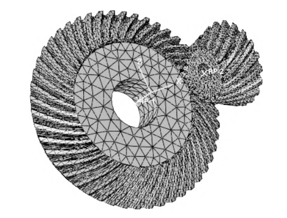
The large mining gear transmission system studied here typically consists of an input shaft, an intermediate shaft, an output shaft, two stages of gears, and multiple bearings. For example, as shown in Figure 1, this configuration forms a complex mechanical structure that requires a detailed dynamic model for analysis.
3.2 Axis Parameterized Modeling
An 8 – degree – of – freedom Timoshenko beam dynamic model is established for the shaft. The mass and stiffness sub – matrices can be determined based on relevant references. By superimposing these sub – matrices at nodes, the overall stiffness matrix of the shaft can be obtained. This matrix can be expressed as a function of the shaft diameter and length parameters, as shown in Equation (1).
| Shaft Parameter | Description |
|---|---|
| Shaft radius () | |
| Shaft length parameter (number of discrete units) |
3.3 Helical Gear Parameterized Modeling
An eight – degree – of – freedom helical gear meshing model is established. Based on the d’Alembert principle, a set of differential equations is derived, resulting in an meshing unit stiffness matrix. The time – varying meshing stiffness is calculated using the potential energy method, which involves calculating various stiffness components such as Hertz stiffness, bending stiffness, shear stiffness, and radial compression stiffness. The overall stiffness of the gear can be expressed as a function of gear parameters such as 齿数 (), 模数 (), 齿宽 (), 压力角 (), and 螺旋角 ().
| Gear Parameter | Description |
|---|---|
| Gear teeth number | |
| Gear module | |
| Gear tooth width | |
| Pressure angle | |
| Helical angle |
3.4 Bearing Dynamics Model
The stiffness of bearings changes during shaft rotation due to the variation in the number of rollers. In this study, the radial time – varying stiffness of the bearing is approximated by a sine curve, and the axial direction is fully constrained. The bearing stiffness can be expressed in terms of parameters such as the static stiffness , the stiffness fluctuation amplitude , the passing frequency , and the initial phase angle .
| Bearing Parameter | Description |
|---|---|
| Bearing static stiffness | |
| Bearing stiffness fluctuation amplitude | |
| Passing frequency | |
| Initial phase angle |
3.5 Tooth Side Clearance
Tooth side clearance has a significant impact on gear operation. When there is clearance, gears may experience larger vibrations or even disengagement at low torques. A piecewise function is used to describe the relationship between tooth side clearance and the relative displacement along the meshing line of the gear pair.
| Tooth Side Clearance State | Condition | ||
|---|---|---|---|
| Normal meshing | |||
| Back tooth meshing | |||
| Disengagement | $\overline{x}_{p e} \leqslant | b | $ |
3.6 Parameterized Fixed – Axis Transmission System Dynamic Model
By assembling the stiffness matrices of shafts, gears, and bearings according to nodes, a parameterized fixed – axis transmission system dynamic model is obtained. The total stiffness matrix of the system can be expressed as a function of multiple macro parameters, including shaft parameters, gear parameters, and layout parameters.
| System Parameter | Description |
|---|---|
| Shaft radius | |
| Gear teeth number | |
| Gear module | |
| Gear tooth width | |
| Pressure angle | |
| Helical angle | |
| Shaft length parameter | |
| First – stage gear installation parameter | |
| Second – stage gear installation parameter |
4. Macro Parameter Optimization Model
4.1 Objective Functions
- Contact Ratio Objective Function (): Contact ratio is an important indicator of gear performance. A larger contact ratio generally leads to more stable transmission and less vibration and noise. For involute helical gears, the total contact ratio is calculated as the sum of the transverse contact ratio and the axial contact ratio. The objective is to minimize the opposite of the total contact ratio.
| Contact Ratio Component | Formula |
|–|–|
| Transverse contact ratio () | |
| Axial contact ratio () | | - Dynamic Characteristics Optimal Objective Function (): Bearing acceleration has a significant impact on the transmission stability and noise of the gearbox. Therefore, the root mean square value of the bearing acceleration is used as an objective function to optimize the dynamic performance of the system.
- Mass Objective Function (): In addition to meeting the requirements of strength and dynamic characteristics, reducing the volume and mass of the gear system is also important. The mass of the transmission system is calculated as the sum of the masses of shafts, gears, etc., excluding the housing mass.
4.2 Design Variables
The macro parameters that affect the dynamic stiffness matrix of the system are selected as design variables. These include gear teeth number, module, tooth width, shaft radius, gear installation position, and phase angle.
| Design Variable | Description |
|---|---|
| Gear teeth number | |
| Gear module | |
| Gear tooth width | |
| Shaft radius | |
| Shaft radius | |
| Shaft radius | |
| Shaft length parameter | |
| First – stage gear installation parameter | |
| Second – stage gear installation parameter | |
| Phase angle | |
| Helical angle |
4.3 Constraint Conditions
- Tooth Number Constraint Conditions: To avoid interference between gears and shafts, certain constraints on the distance between gears and shafts are imposed.
- Shaft Diameter Strength Constraint: The diameter of the shaft must meet the strength requirements related to the transmitted power and rotational speed.
- Transmission Ratio Constraint: The transmission ratio of the two – stage transmission system is constrained within a certain range to ensure the proper functioning of the system.
- Strength Constraint Conditions: This includes constraints on the contact fatigue strength of gear teeth surfaces, the bending fatigue strength of gear roots, and the torsional strength of shafts.
4.4 Algorithm Selection
Due to the strong nonlinearity of the optimization problem, a population – based optimization algorithm is required. The NSGA – Ⅱ algorithm, which considers crowding degree and elitist strategy, is chosen. It uses a crowding degree comparison operator to reduce computational complexity and avoid local convergence.
5. Case Study and Results
5.1 Case Introduction
A large mining gearbox from a certain company is selected as an example for multi – objective optimization of macro parameters. The rated speed of the reducer, load torque, and initial macro parameters of the transmission system and gears are provided.
| Gear Design Parameter | Value | System Layout Parameter | Value |
|---|---|---|---|
| 1st active wheel teeth number | 21 | Axis 1 radius (m) | 0.1 |
| 1st passive wheel teeth number | 92 | Axis 2 radius (m) | 0.1 |
| 2nd active wheel teeth number | 26 | Axis 3 radius (m) | 0.1 |
| 2nd passive wheel teeth number | 107 | Axis length parameter | 9 |
| 1st module (mm) | 14 | 1st parameter | 2 |
| 2nd module (mm) | 14 | 2nd parameter | 257 |
| 1st tooth width (mm) | 300 | Phase angle (°) | – |
| 2nd tooth width (mm) | 170 | – | – |
| 1st helical angle (°) | 10 | – | – |
| 2nd helical angle (°) | 14 | – | – |
5.2 Optimization Results
- System Layout: After multi – objective optimization, the layout of the shaft system becomes more compact, which is beneficial for manufacturing and cost reduction.
- Dynamic Characteristics: By comparing the initial parameters with the optimized parameters in a MATLAB program, it is found that the root mean square value of the gear dynamic load is effectively reduced. When considering different optimization strategies, different trade – offs between dynamic performance and system mass are observed.
| Optimization Strategy | Optimization Target 1 (N) | Optimization Target 2 () |
|–|–|–|
| A1 | 7796 | 1.15 |
| B1 | 9469 | 0.41 |
| B2 | 6327 | 0.53 |
| B3 | 5283 | 0.76 | - Frequency Domain Analysis: The time – domain responses of the first – stage and second – stage gear dynamic meshing forces are obtained and transformed into the frequency domain. The results show that the amplitudes of the meshing forces are significantly reduced after optimization, and the energy of most frequency components is also decreased.
5.3 Validation of Optimization Parameters
By substituting the parameters of strategy B2 into the program, the dynamic meshing forces of the gears before and after optimization are compared. The results show that the amplitudes of the meshing forces are reduced, and the mean value of the meshing force also changes. This validates the effectiveness of the optimization method.
6. Conclusion
- A parameterized dynamic model for large mining gear transmission systems has been successfully established using the finite element method. The model reflects the mapping relationship between design parameters, layout parameters, and dynamic responses.
- The NSGA – Ⅱ algorithm has proven to be effective for optimizing the dynamic performance of large mining gear transmission systems. Through multi – objective optimization, significant improvements in dynamic meshing forces and volume reduction have been achieved.
- For large mining gear transmission systems, multi – objective optimization considering both dynamic characteristics and volume is more suitable for system design. Future research could focus on further improving the optimization model and exploring more efficient optimization algorithms for even better performance of these critical systems.
In conclusion, the research presented in this article provides a valuable theoretical and practical reference for the design and optimization of large mining gear transmission systems, contributing to the improvement of their reliability and performance in the mining industry.