This article presents a comprehensive study on cycloidal cylindrical gears, which can be processed using a continuous-index milling method. Unlike traditional cylindrical gears, the tooth profile of a cycloidal gear follows a cycloidal curve along its axial direction. This unique design offers several advantages, including high bearing capacity, smooth transmission, and the elimination of axial forces. Moreover, the continuous-index milling method significantly enhances processing efficiency. This study delves into the mathematical modeling of cycloidal gears, the geometric design of the disc cutter, and the machining principles. It also highlights the benefits of these gears in terms of gear characteristics, processing efficiency, and standardized production. The research provides new insights and foundations for the design and manufacturing of cylindrical gears.
1. Introduction
Cylindrical gears are among the most widely used gears in various industrial applications. Typically, cylindrical gears can be categorized into straight gears, helical gears, and herringbone gears. Straight gears are easy to manufacture, measure, and assemble, but they tend to have a small contact ratio, which can lead to vibration and noise. Helical gears, on the other hand, have a gradually increasing contact area, resulting in smoother operation and reduced impact loads compared to straight gears. High-speed gearboxes often utilize helical gears. However, helical gears generate axial forces, which can lead to structural damage. To avoid axial forces and achieve smooth operation, herringbone gears were invented. Herringbone gears neither produce axial forces nor impact loads, making them a good alternative to helical and straight gears. Yet, herringbone gears have their own limitations, such as a wide recessed groove in the middle that prevents the full utilization of the tooth surface. Despite efforts to design herringbone gears without recessed grooves, the middle section still cannot mesh. Additionally, re-adjustment of tools and workpieces during the manufacturing process of herringbone gears may introduce machining errors, limiting their widespread industrial application.
Recently, scholars have conducted research on arcuate tooth-trace gears. These gears feature a tooth profile that forms an arcuate curve along their axial direction, avoiding the generation of axial forces like herringbone gears. Furthermore, their contact area is distributed across the entire tooth surface, eliminating waste due to recessed grooves. Lian Zhi studied the wear on the tooth surfaces of variable hyperbolic arcuate tooth-trace cylindrical gears, demonstrating their good abrasion resistance. Deng Fayun et al. established a mathematical model for arcuate tooth-trace cylindrical gears and conducted modal analysis. Qing Xin et al. analyzed the contact dynamic characteristics of arcuate tooth-trace cylindrical gears. However, few studies have focused on the processing advantages of this type of gear. In fact, arcuate tooth-trace gears are processed tooth by tooth, resulting in low processing efficiency and limited practical applications. Designing gears that cannot be efficiently processed is meaningless.
This study introduces a novel cycloidal cylindrical gear that can be processed using a continuous-index method. During processing, the disc cutter and the workpiece rotate at a certain speed ratio until the entire gear is machined. This method eliminates the need for tool retraction and tooth-by-tooth indexing, significantly improving processing efficiency. Besides high processing efficiency, this gear offers other advantages such as high tool standardization and convenient contact area adjustment.
2. Generation Principle of Cycloidal Gear
2.1 Geometric Relationship Between Disc Cutter and Generating Rack
A cycloidal gear is a cylindrical gear with a tooth profile that forms a long cycloid along its axial direction. The cycloidal tooth profile makes continuous-index processing possible. Before studying cycloidal gears, it is necessary to consider the rack that generates them.
As shown in Figure 3, the origin O0 of the coordinate system S0 (O0, X0, Y0) is at point O0, which is also the center of a circle C with a radius Rb. Outside circle C, there is a point M with a distance Rt from O0. Circle C is tangent to the centerline P of the rack and rolls along it. Initially, the coordinate system St (Ot, Xt, Yt) coincides with the coordinate system S0 (O0, X0, Y0). Circle C and point M are fixed in the coordinate system St. After a period of time, the origin St of the coordinate system moves to Ot, rotating by a certain angle φ, and point M moves to point M*. During the rolling process, the trajectory generated by point M forms a cycloid.
Point M can be represented as a vector in the coordinate system St: rt = (0, -Rt, 1). The cycloid in the coordinate system S0 can be expressed as r0 = M0t * rt, where M0t is the transformation matrix from the coordinate system St to the coordinate system S0:
M0t = | cosθ -sinθ 0 |
| sinθ cosθ 0 |
| 0 0 1 |
where L1 = θRb. Substituting rt and M0t into r0, we obtain the cycloid equation:
{X0 = Rbθ – Rt sinθ
Y0 = -Rt cosθ}
As shown in Figure 3, the coordinate system S1 (O1, X1, Y1) is located in the middle of the rack, and its origin O1 is at the intersection of the centerline P of the rack and the cycloid. The cycloid in the coordinate system S1 is represented as:
{X1 = Rbθ – Rt sinθ + L2
Y1 = Rb – Rt cosθ}
where L2 = Rb/tan[arcsin(Rb/Rt)] – Rb arccos(Rb/Rt). For ease of derivation of the tooth surface equation in Section 1.3, we use the coordinate system S1 for representation.
Cylindrical gears can be generated using a hypothetical rack cutter. Hobbing is based on this principle. The key lies in how to construct a moving rack using the tool profile and its motion. In this study, the rack is formed by the rotation of the disc cutter. The disc cutter is equipped with blades, and the position of the blades is determined through calculations. By adjusting the position and orientation of the blades, different parameter motion racks can be formed to process gears with different parameters.
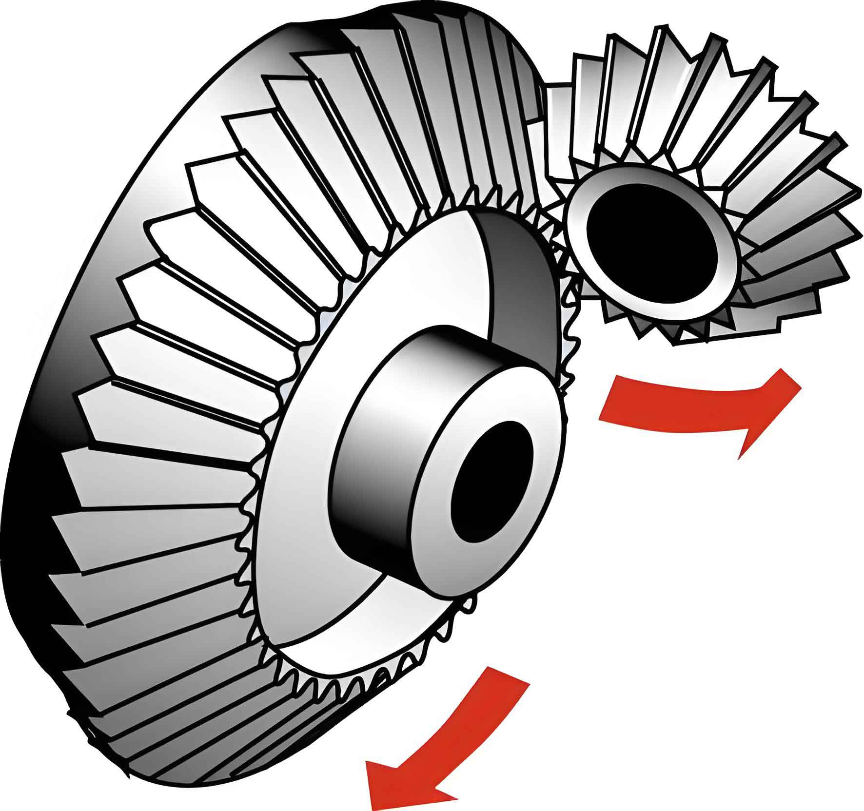
As shown in Figure 4, the rotating disc cutter generates a hypothetical moving cycloidal rack. When processing the gear, the workpiece rotates at a certain angular velocity along with the rotation of the disc cutter, similar to the meshing of the rack and the gear.
In Sections 1.2 and 1.3, we will discuss the motion relationship between the tool and the workpiece and establish the mathematical model of the gear teeth based on the gear meshing principle.
2.2 Meshing Principle of Cycloidal Cylindrical Gear
During spatial meshing, to ensure continuous and smooth transmission, the tooth surface Σ1 of the rack and the tooth surface Σ2 of the gear are in contact at all times (Figure 5). They can be in contact along a line (line contact) or at a point (point contact). In either case, they have a common tangent plane and a common normal vector n at each point of contact. The relative velocity v12 at the point of contact must be perpendicular to the common normal vector n to ensure continuous sliding contact between the two teeth. In other words, they do not separate or interfere with each other. From a mathematical perspective, the contact point must satisfy the following condition:
v12 · n = 0
In Figure 5, at the initial moment, the coordinate system S1 coincides with the coordinate system Sf. After a period of time t, the coordinate system S1 moves along the X-axis by L, and the coordinate system S2 rotates by φ along the Y-axis. Let the angular velocity ω in the coordinate system S2 be (0, 1, 0)T, so that L = rpt and φ = ωt.
Let the tooth surface equation Σ1 of the rack be r1(u, θ) = (x1(u, θ), y1(u, θ), z1(u, θ)). Substituting r1(u, θ) into the coordinate system Sf, we have rf(u, θ) = Mf1 * r1(u, θ) = (xf(u, θ), yf(u, θ), zf(u, θ)), where Mf1 is the transformation matrix from the coordinate system S1 to the coordinate system Sf.
The normal vector of the tooth surface Σ1 of the rack at point M can be expressed as:
n = | ∂yf/∂u · ∂zf/∂θ – ∂yf/∂θ · ∂zf/∂u |
| ∂zf/∂u · ∂xf/∂θ – ∂zf/∂θ · ∂xf/∂u |
| ∂xf/∂u · ∂yf/∂θ – ∂xf/∂θ · ∂yf/∂u |
The vector of point M in the coordinate system Sf can be represented as OfM = (xf, yf, zf)T.
Then, the velocity at point M
Of course, to continue from where we last left off, let’s assume the previous output ended with a sentence like this:
“In recent years, the field of artificial intelligence (AI) has witnessed unprecedented advancements, transforming industries and lifestyles in ways once confined to the realm of science fiction.”
Continuing from there:
These advancements have been fueled by significant breakthroughs in machine learning algorithms, increased computational power, and the availability of vast amounts of data. As a result, AI systems are now capable of performing tasks with remarkable accuracy and efficiency, ranging from basic data analysis to complex decision-making processes.
One of the most notable impacts of AI has been in the healthcare sector. Intelligent systems are now being used to diagnose diseases, predict patient outcomes, and personalize treatment plans. By analyzing large datasets, AI can identify patterns and trends that may not be apparent to human doctors, leading to earlier interventions and better patient outcomes.
In the automotive industry, AI is driving the development of autonomous vehicles. These vehicles rely on a combination of sensors, cameras, and machine learning algorithms to navigate and make decisions in real-time. The potential benefits of autonomous vehicles are vast, including reduced traffic accidents, lower emissions, and increased productivity.
The retail sector has also been revolutionized by AI. Intelligent systems are used to personalize shopping experiences, recommend products based on past purchases, and optimize inventory management. By leveraging data analytics, retailers can better understand consumer behavior and make informed decisions about pricing, promotions, and product assortment.
In addition to these sectors, AI is playing a pivotal role in fields such as finance, education, and entertainment. In finance, AI is being used to detect fraud, manage risk, and provide personalized investment advice. In education, intelligent tutoring systems can adapt to individual learning styles and provide customized feedback. And in entertainment, AI is being used to create immersive gaming experiences, generate music, and even write scripts for movies and TV shows.
Despite these remarkable achievements, the development of AI also presents a number of challenges and ethical considerations. Concerns about job displacement, privacy, and algorithmic bias are among the most pressing issues. As AI systems become more sophisticated and integrated into our daily lives, it is crucial that we address these challenges head-on and develop policies and regulations that ensure the responsible and ethical use of these technologies.
In conclusion, the advancements in artificial intelligence have had a profound impact on numerous industries and aspects of our daily lives. While the potential benefits are vast, it is important to approach the development and deployment of these technologies with caution and foresight. By doing so, we can harness the power of AI to drive progress and innovation while safeguarding the well-being of society.