Bevel gears play a crucial role in mechanical transmission, being widely used in aerospace, automotive, and construction machinery transmissions. The quality of their tooth surfaces is an important indicator of meshing transmission performance. However, in the actual quality assessment of bevel gears, there are often difficulties in obtaining process parameters, and establishing theoretical tooth surface models is a complex task. This article studies a relative evaluation method for the quality of bevel gears to address these issues.
1. Introduction
In the three-dimensional measurement of bevel gears, the traditional method of using 45 discrete grid points for contact measurement is inefficient and struggles to obtain full tooth surface data. With the extensive application of optical measurement technology in gear measurement, this problem of insufficient tooth surface measurement points has been effectively compensated. Theoretical calculation can be used to assess the quality of bevel gears, but it often relies on the complex tooth surface mathematical model, which is not only affected by the design parameters of the bevel gear but also related to the machine adjustment parameters. In practical quality assessment, it is often difficult to obtain the theoretical mathematical model of the tooth surface due to the unavailability of process parameters. Therefore, the relative evaluation method becomes a more ideal choice in such situations. This article obtains the three-dimensional tooth surface information of bevel gears through optical measurement methods, studies a relative evaluation method for the quality of bevel gears, overcomes the problems of relying on complex theoretical models and insufficient information acquisition in traditional bevel gear measurements, and further reflects the stability of the bevel gear production process at the processing site.
2. Relative Evaluation Principle
2.1. Theoretical Tooth Surface of Bevel Gears
Figure 1 shows the three-dimensional coordinate system of the bevel gear, where the z-axis of the coordinate system coincides with the rotation axis of the bevel gear, the xOy plane is perpendicular to the z-axis and coincides with the end section of the large end of the bevel gear, and the origin o is located at the intersection of the z-axis and the end face of the large end of the gear. The tooth surface equation of the bevel gear can be expressed as: .
2.2. Establishing the Reference Tooth Surface
A workpiece gear with better tooth surface quality is selected from the same batch of bevel gears as the reference gear, and the three-dimensional data point set of the tooth surface can be expressed by a discretization mathematical model. As shown in Figure 2, two directions U and V are taken on the tooth surface to establish the coordinate system, where the U direction points from the tooth root to the tooth top, and the V direction points from the large end to the small end of the bevel gear. The coordinate W is used to represent the sequence number of each tooth. Based on the above special U-V-W coordinate system, the discretized point cloud data of the same side tooth surface of the reference gear can be represented by a structured three-dimensional model.
3. Gear Three-Dimensional Measurement System
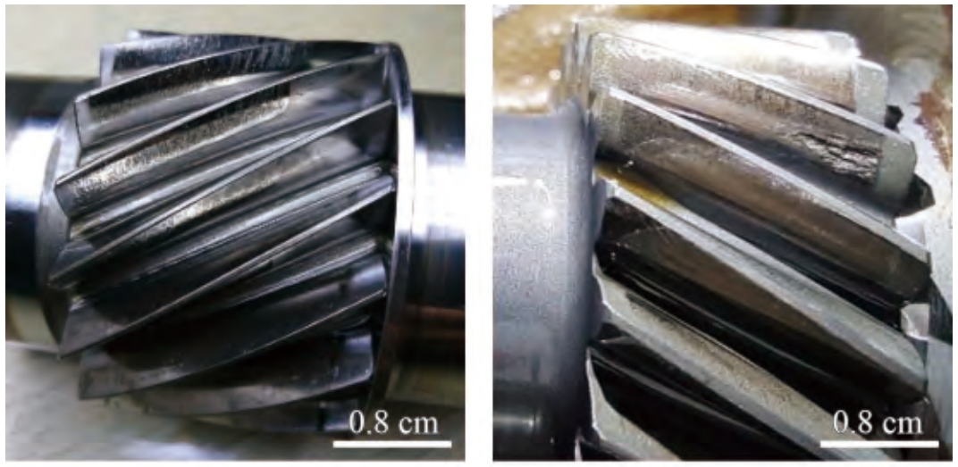
Figure 5 shows the three-dimensional measurement experimental device of the bevel gear, where a line-structured light sensor is carried on the gear measurement center. The measured gear is installed on the instrument rotary spindle and rotates at a certain speed with the spindle. The line-structured light sensor is installed on the base of the linear moving shaft through the fine-tuning platform, which can realize the adjustment of any pose in space. In the measurement process, the rotary angle signal of the spindle is used as an external trigger source to trigger the sensor to collect signals, and the contour acquisition data of the tooth surface is obtained in real-time. The sensor selects the Keyence LJ-V7000 series line-structured light sensor, with a nominal distance of 60mm, a measurement range of the line width of 13.5 to 15mm, a height measurement range of ± 8mm, and a repeat accuracy of 0.4μm. As shown in Figure 6, the 9-tooth spiral bevel gear is selected for the measured gear, and the basic parameters are shown in Table 1.
| Basic Parameters | Values |
|---|---|
| Tooth Number | 9 |
| Module | 3.877mm |
| Spiral Angle | 46.50 |
| Pitch Cone Angle | 13.0086° |
| Face Cone Angle | 18.0078° |
| Root Cone Angle | 12.0069° |
The coordinate system of the measurement system is established as shown in Figure 7, where is the gear coordinate system, is the world coordinate system, and o is the sensor coordinate system. The z-axis of the gear coordinate system coincides with the gear axis and rotates with the gear; the z-axis and the origin of the world coordinate system respectively coincide with the z-axis and the origin of the gear coordinate system; the origin O of the sensor coordinate system is located at the center point of the outgoing laser line, and the plane is parallel to the laser plane.
Through the line-structured light gear measurement model, the measured three-dimensional tooth surface data of the bevel gear can be obtained as:
In the equation, is the coordinate value of the measured point in the gear coordinate system, ; the matrix is the transformation matrix about the gear rotation angle φ and the sensor pose parameters [α, β, x, a, b, c] [5]; D is the coordinate value of the measured point in the sensor coordinate system, .
4. Experimental Verification
4.1. Acquisition of the Reference Tooth Surface
A workpiece gear with better quality is selected from a batch of spiral bevel gears with the same parameters as the reference gear, and all 9 tooth surfaces of the reference gear are taken as the reference tooth surfaces, and the three-dimensional data point cloud is shown in Figure 8.
4.2. Acquisition of the Measured Tooth Surface
The measured gear is measured in the three-dimensional measurement experimental device of the bevel gear, and the original data of the actual tooth surface of the gear is obtained, and the three-dimensional point cloud of the measured spiral bevel gear is obtained through coordinate transformation, as shown in Figure 9.
Due to the offset of the line-structured light sensor in the x-axis direction and the influence of the tooth surface curvature of the spiral bevel gear and the laser re-reflection, only one side of the tooth surface can be measured each time. In this experiment, the convex surface of the tooth of the spiral bevel gear is selected for measurement, with about 3.2 million points on each tooth surface. In addition, the actual three-dimensional point cloud data of the gear is affected by the width of the sensor laser beam and the spatial pose, and the data in the z-axis direction is concentrated between -3mm and 3mm. If it is desired to obtain the point cloud data of the entire tooth surface on both sides of the spiral bevel gear, it can be achieved by moving the sensor symmetrically along the xc-axis and moving it at equal distances along the z-axis. According to the division rule of the tooth surface evaluation area of the spiral bevel gear (the top and bottom ends of the tooth profile are respectively located at 5% of the tooth height along the tooth profile direction, and cannot exceed 0.6mm), the evaluation area is extracted from the original point cloud data, and high-frequency interference is filtered out. The actual tooth surface evaluation area is shown in Figure 10.
4.3. Deviation Calculation and Analysis
In order to facilitate the comparison and analysis between the actual tooth surface and the reference tooth surface, all the discrete points of the tooth surface are projected onto the axial section. By matching the point cloud coordinates of the reference tooth surface and the actual tooth surface, the normal deviation of the actual tooth surface relative to the reference tooth surface is compared (see Figure 11), and the maximum normal deviation value of the tooth surface is 2.166μm, and the minimum normal deviation value is -2.284μm.
Five bevel gears with the same parameters in this batch are randomly selected for relative quality assessment with the reference gear, and the normal deviation results are shown in Table 2. It can be seen that the relative assessment results of the selected gears have good consistency, which further reflects that the production process of this batch of bevel gears has good stability.
| Parameters | Gear 1 | Gear 2 | Gear 3 | Gear 4 | Gear 5 |
|---|---|---|---|---|---|
| Maximum Normal Deviation Value | 2.026 | 2.146 | 2.441 | 2.555 | 2.496 |
| Minimum Normal Deviation Value | -3.105 | -2.057 | -2.295 | -2.209 | -1.634 |
5. Conclusion
This article studies a relative evaluation method for the three-dimensional measurement of spiral bevel gears to address the problems of difficult theoretical tooth surface construction caused by the difficulty in obtaining process parameters and the complexity of machine adjustment parameters in the actual quality assessment of bevel gears. This method selects a workpiece gear with higher quality in the same batch as the reference gear, and takes the averaged tooth surface of the reference gear as the reference tooth surface. Combined with the three-dimensional measurement technology of the line-structured light gear, more abundant actual three-dimensional tooth surfaces are obtained, and compared and analyzed with the reference tooth surface, thereby obtaining the normal deviation and assessment results of the measured gear.
The experimental results show that when it is difficult to construct a theoretical tooth surface, the relative evaluation method for the quality of bevel gears is a more ideal solution. This method not only overcomes the problems of relying on complex theoretical models and insufficient information acquisition in traditional bevel gear measurements, but also can reflect the stability of the bevel gear production process while assessing the quality of the gear. In future research, information collection and quality assessment of the entire tooth width should also be expanded to better characterize the quality of the entire tooth surface and reliably monitor the stability of the production process at the site.