This paper conducts a study on the fatigue life prediction of the gear pair aiming at the gear fatigue failure problem of high-speed and heavy-duty aviation fuel gear pumps. Firstly, the allowable safety factor and meshing contact stress of the gear are analyzed by using the Hertz contact model theory, cantilever beam equivalent model and other analytical methods and finite element method. Secondly, the finite element calculation of tooth surface contact fatigue strength and tooth root bending fatigue strength is carried out. Finally, the gear fatigue life prediction under three typical working conditions is carried out by using the finite element method. The research results show that the gear contact and bending strength safety factors and contact stress all meet the material strength requirements, the gear tooth surface reliability is not less than 99.97%, and the predicted fatigue life is 5,027 hours, which meets the design life requirements of this type of gear pump.
1. Introduction
The external meshing gear pump is often used as the main fuel pump of the aeroengine due to its advantages such as simple structure, small volume, light weight, and strong anti-pollution ability. Currently, the problems of the aeroengine fuel pump mainly focus on how to improve reliability and lifespan. The gear, as the main load-bearing component of the gear pump, has a large contact pressure on the tooth surface, which is prone to causing tooth surface wear and fatigue. It is a weak link of the gear pump, and the load-bearing performance and lifespan of the gear largely determine the reliability and service life of the gear pump. Therefore, it is necessary to conduct in-depth analysis of the reliability and fatigue life of the pump’s gear to lay a theoretical foundation for the high-pressure and high-speed of the fuel pump.
Gear fatigue failure is the main failure mode of the aviation fuel gear pump. There are many factors affecting gear fatigue, including material properties, tooth profile parameters, working conditions, tooth surface friction, and medium characteristics. In order to improve the working reliability of gears, scholars at home and abroad have carried out a large amount of research work. Enesi Y. et al. observed the failed gears through optical measurement means and concluded that the wear of the sample gears was due to the dislocation of the gears caused by the cyclic load acting on the gear surface; Shuting Li et al. studied the stress and deformation of the gears by using the Hertz classic elastic contact model, finite element contact model and mathematical programming method around the gear contact problem; Liu Cheng analyzed the multi-tooth nonlinear meshing process by using the ABAQUS finite element method, and measured the tooth root bending stress by using the bench test, and the theoretical prediction results are consistent with the experimental change trend; Hu Wanhui studied the gear contact stress and bending stress by using the finite element numerical simulation method, and extended the solution method of the maximum tensile stress of the cantilever beam structure to the calculation of the gear tooth root. Anı Ural et al. simulated the expansion process of the 3D crack of the gear based on the theory of linear elasticity and the Franc3D finite element software, and considered the influence caused by the fatigue crack closure due to the material plasticity and the transient load movement in the research process; Guo Songling compiled the fatigue load spectrum by using the double-parameter rainflow counting method, modified the S-N curve of the structural material according to the GL specification, performed the static solution of the structure by using the finite element method, and calculated the structural fatigue reliability. Davoli et al. assumed the smooth contact condition of the gear and applied the multi-axial fatigue criterion to the calculation of the gear contact stress.
In summary, the research methods of domestic and foreign scholars in predicting the reliability and lifespan of gears mainly involve theoretical analysis, finite element analysis and experimental methods. The gear fatigue contact test is carried out on the basis of the general material fatigue test, and its test data has a large dispersion and requires sufficient test data, and the test period is long. Especially, the aeroengine fuel gear pump is expensive, which is a typical small sample research object, and it is very limited to study its fatigue and reliability by using sufficient test means. Therefore, this paper conducts the fatigue life characteristic prediction research of the gear based on the finite element simulation method to ensure the reliability and stable operation of the high-speed and heavy-duty gear pump.
2. Fuel Gear Pump Model
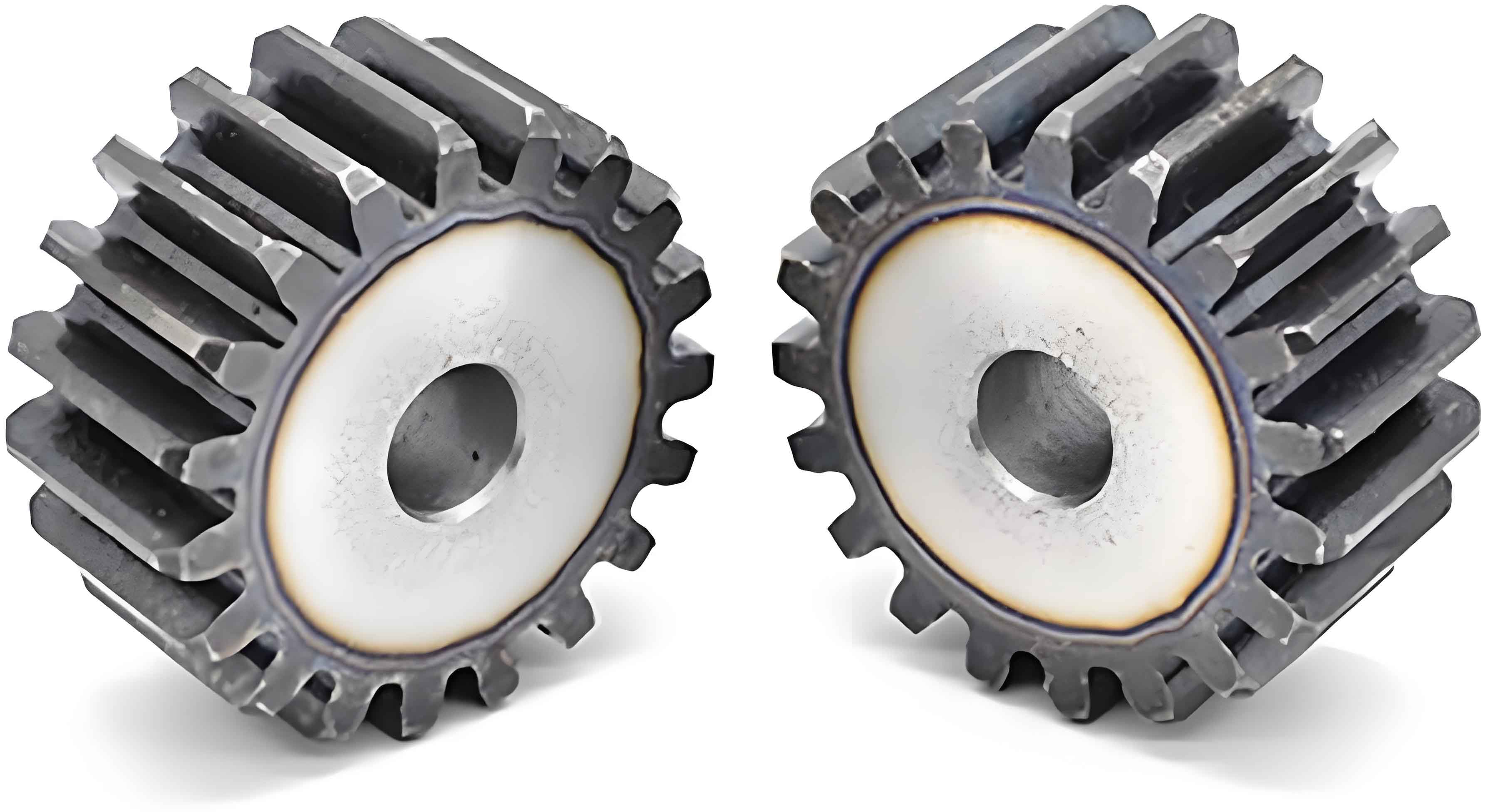
The fuel gear pump supplies fuel to the main combustion chamber of the aeroengine through the meshing transmission of the gear pair, and its main components include the gear, shaft system, housing, and other structures (as shown in Figure 1).
The object studied in this paper is a certain type of high-speed and heavy-duty fuel gear pump of the aeroengine, with a maximum speed of 8,500 r/min, a pressure gain of 10.5 MPa, and a design life of not less than 5,000 hours. The material selected for the gear pair is 20Cr2Ni3A, and the heat treatment process is 820 – 840 °C, oil or warm water cooling + 400 – 500 °C, oil or water cooling. This material is a kind of high-quality alloy steel with high strength, good toughness and quenching property.
Finite element simulation. Due to the elastic deformation of the tooth surface of the gear pair under load during the meshing process affecting the reliability and lifespan of the gear pump, the accuracy of solving such highly nonlinear contact problems by applying the traditional Hertz elastic simplified model is low. Therefore, this paper predicts the tooth surface contact situation based on the ANSYS Workbench finite element platform.
Firstly, mesh division is carried out, including free mesh and mapped mesh. Compared with the free mesh, the mapped mesh has a smaller number of elements, which can reduce the calculation amount and improve the calculation accuracy. In this section, the mapped mesh is used to divide the gear structure. Due to the strict requirements of the mapped mesh on the structure shape, it is necessary to divide the wheel body into structures that can be divided into mapped meshes, and then merge the divided parts of the driving and driven wheels respectively, so that the mesh nodes on the divided surface are shared. The divided gear pair is shown in Figure 2, and the final gear pair mesh model is shown in Figure 3.
The equivalent stress distribution cloud map of the typical moments in the gear meshing process is obtained as shown in Figure 4(a) – (b). It can be seen from Figure 4 that the gear undergoes a meshing process from double teeth – single tooth – double teeth in a complete meshing cycle, and the contact stress gradually increases from small, and then decreases. The maximum equivalent stress of the gear contact is 1,040 MPa, which occurs at the moment of single tooth meshing, as shown in Figure 4(b), and the other moments are all double tooth meshing moments. Generally speaking, the double tooth meshing stress is much smaller than the stress level of single tooth meshing. This is because when the double tooth meshes, the gear load is borne by two gears together. At this time, the gear stiffness is larger than that of single tooth meshing, and the gear elastic deformation is small. Therefore, compared with the single tooth contact stress, the double tooth contact stress is smaller. The yield strength of the gear material is 1,331 MPa, and the calculated contact stress of the gear is 1,040 MPa, which does not exceed the material yield limit, indicating that the gear meets the strength requirements and can be used normally within the design life.
3. Gear Fatigue Life Prediction
After long-term operation of the gear pump, high-cycle fatigue will occur. When the gear rotates, it is subjected to the action of cyclic stress, and it is the most prone component to fatigue failure, which will affect the service life of the gear pump. Therefore, it is necessary to predict its fatigue life. The fatigue life prediction methods are generally divided into three types: fatigue simulation test method, theoretical analysis method and numerical simulation method.
In this paper, the life prediction analysis is carried out by the numerical simulation method, and the gear stress level is different under different working conditions. The gear fatigue life under three typical working conditions of the gear pump is predicted in this paper, and the working condition parameters are shown in Table 1.
| Rotation speed (r/min) | Inlet pressure (MPa) | Outlet pressure (MPa) |
|---|---|---|
| 4,750 | 2.13 | 4.23 |
| 3,520 | 4.5 | 7.5 |
| 5,200 | 6.5 | 10.5 |
The numerical solution of the gear meshing process under the conditions in Table 1 is carried out, and the finite element calculation result is taken as the load spectrum for the gear fatigue analysis. The physical properties of the gear 20Cr2Ni3A are defined, and the comprehensive surface treatment coefficient is applied to modify the material S-N curve. The calculation formula of the comprehensive surface treatment coefficient is as follows:
Among them, the gear surface treatment factor is 0.95, the user-defined factor is 1, and the roughness factor is 1.5.
Figure 5(a) – Figure 7(a) are the gear fatigue damage cloud maps of the gear under three typical working conditions, and the gear damage value refers to the damage suffered by the gear for one cycle of the gear load spectrum, which characterizes the damage degree of the gear. The larger the damage value, the higher the damage degree. Figure 5(b) – Figure 7(b) are the gear fatigue life cloud maps of the gear under three working conditions.
It can be seen from the gear fatigue loss distribution cloud maps in Figure 5(a) – Figure 7(a) that the fatigue damage degree and damage distribution range are different under different working conditions. The maximum damage value of the gear in Working Condition 1 is , the maximum damage value in Working Condition 2 is , and the maximum damage value in Working Condition 3 is . The maximum damage of the gear under each working condition appears at the tooth root, which is due to the action of tensile and compressive alternating loads at the tooth root, and the tooth root structure shape leads to easy stress concentration at the tooth root, and the tensile stress at the tooth root is prone to cracking, resulting in fatigue failure.
The minimum fatigue life calculation values of the gear are extracted from Figure 5(b) – Figure 7(b): the minimum fatigue life of the gear in Working Condition 1 is revolutions, the minimum life in Working Condition 2 is revolutions, and the minimum life in Working Condition 3 is revolutions, indicating that the gear with a larger damage degree has a shorter life; the low-life area of the gear is mainly concentrated at the tooth root, indicating that cracks are prone to initiation at the tooth root, which is the first failure position, which is consistent with the actual situation.
Combining the usage rate of the gear pump working conditions, the damage degrees under each load level are calculated, and the results are shown in Table 2.
| Rotation speed (r/min) | Time (min) | Damage degree |
|---|---|---|
| 4,750 | 185 | |
| 3,520 | 8 | |
| 5,200 | 2 |
According to the Miner cumulative damage principle: if the total damage value of the gear reaches 1, the gear is considered to fail. After the gear completes the working condition in Table 2 once, the cumulative damage degree of the gear , and the recyclable number of times before the gear fails.
The gear fatigue life is expressed in the form of time life :
Among them, is the working time of the gear for one load cycle, hours; is the number of cycles, times. According to the linear fatigue cumulative damage theory (Miner theory), the service life of the gear pump can be calculated as hours.
4. Conclusion
Through the study of the fatigue life prediction method of the tooth profile, the main research conclusions obtained in this paper are as follows.
(1) The numerical simulation of the transient meshing process of the gear is carried out based on the ANSYS finite element method, the yield strength of the gear material is 1,331 MPa, and the calculated contact stress of the gear is 1,040 MPa, which does not exceed the material yield limit, indicating that the gear meets the strength requirements.
(2) The fatigue life of the gear under three typical working conditions is predicted through the Miner cumulative damage principle and Ansys simulation, and the predicted service life of the gear pair is 5,027 hours, which is higher than the design life requirement of 5,000 hours of this type of gear pump, indicating that the design and analysis methods have high calculation accuracy.