1. Introduction
Gear transmission is a fundamental and crucial component in mechanical systems, renowned for its capabilities such as high – power transmission, high efficiency, and accurate transmission ratio. Among various types of gears, the arc cylindrical gear has attracted significant attention in recent years due to its unique advantages.
Compared with traditional involute spur and helical gears, arc cylindrical gears possess a distinct tooth – shape structure, which endows them with excellent performance. Involute spur cylindrical gears experience sudden loading and unloading of loads along the entire tooth width during meshing, resulting in substantial impact and noise, as well as poor transmission stability. Helical cylindrical gears, although having the advantages of large bearing capacity, high (coincidence degree), and stable transmission due to the inclined contact line of the tooth profile surface, suffer from a relatively large axial force during the transmission process. In contrast, arc cylindrical gears, with a tooth – shape structure similar to herringbone gears, exhibit high ,small axial load, and strong bearing capacity. Moreover, during the meshing process of arc cylindrical gears, the engagement and disengagement of each pair of teeth occur gradually. This not only eliminates the meshing impact phenomenon of spur gears but also avoids the axial force problem of helical gears, thus ensuring better transmission performance. Additionally, the arc – shaped tooth line of arc cylindrical gears allows for a small rotation along the tooth line during installation without affecting the meshing transmission, demonstrating strong adaptability to the parallelism error of the gear pair installation. However, the widespread application of arc cylindrical gears in mechanical transmission is currently limited by the need for special processing equipment and milling cutters for tooth cutting. This article aims to comprehensively explore the design, manufacturing methods, and potential applications of arc cylindrical gears, with the hope of promoting their further development and utilization.
2. Basic Parameters and Design Calculation of Arc Cylindrical Gears
2.1 Fundamental Basis – Basic Rack of Arc Cylindrical Gears
When studying arc cylindrical gears, the basic rack serves as the foundation. As shown in Figure 1 (insert the image of the basic rack of arc cylindrical gears here, with clear markings of relevant parameters), the basic rack of an arc cylindrical gear consists of convex and concave surfaces of the tooth, denoted as \(p\) and \(q\) respectively. These two surfaces are parts of two cones \(P\) and \(Q\). The radius of the cone at the pitch circle is \(R\), and the distance between the axes of the two cones is \(t/2\). The width of the rack is \(b\). The \(A – A\) section represents the middle section of the rack, and the \(B – B\) section is the pitch plane of the rack. The tooth profile in the \(A – A\) section exhibits an involute shape.
2.2 Similarities with Involute Spur Cylindrical Gears in Design
Research has indicated that the tooth profile of an arc cylindrical gear in the middle section of the tooth is identical to that of an involute spur cylindrical gear. Consequently, the design calculation of arc cylindrical gears can draw on the methods used for involute spur cylindrical gears. The basic geometric parameters of arc cylindrical gears include modulus \(m\), number of teeth \(z\), pressure angle \(\alpha\), addendum coefficient \(h_{a}^{*}\), and clearance coefficient \(c^{*}\).
2.3 Design Process
The design process of arc cylindrical gears can refer to that of involute spur cylindrical gears, and the design criteria are also similar. In the design of spur cylindrical gears, the main failure modes are tooth surface fatigue pitting and tooth root fatigue fracture. Therefore, depending on the application scenario of the gear transmission, design calculation criteria such as tooth surface contact fatigue strength or tooth root bending fatigue strength can be selected for design calculation.
For arc cylindrical gears, the design process is as follows:
- Select the gear material, heat treatment method, and accuracy level. Different materials and heat treatment methods can significantly affect the mechanical properties of gears. For example, high – quality alloy steels with appropriate heat treatment can improve the wear – resistance and fatigue strength of gears. The accuracy level of gears directly impacts the transmission accuracy and noise level.
- Determine the corresponding design criteria based on the operating conditions. If the gear is used in a high – load and high – speed transmission system, the tooth surface contact fatigue strength design criterion may be more suitable; if it is in a system with large impact loads, the tooth root bending fatigue strength design criterion should be considered.
- Calculate and determine the number of teeth and modulus of the small gear. When selecting the number of teeth of the small gear, the problem of undercutting needs to be considered, and the number of teeth of the small gear should satisfy \(z_{min}\leq z_{1}\). Once the number of teeth of the small gear is determined, the number of teeth of the large gear can be calculated according to the gear transmission ratio \(z_{2}=iz_{1}\).
- Calculate the main dimensions of the arc cylindrical gear according to the geometric dimension calculation formulas in Table 1.
- Check and verify the strength of the arc cylindrical gear to ensure that the designed gear can meet the actual working requirements.
3. Cutting Processing of Arc Cylindrical Gears
3.1 Cutting Methods
3.1.1 Rotating Cutter Head Method
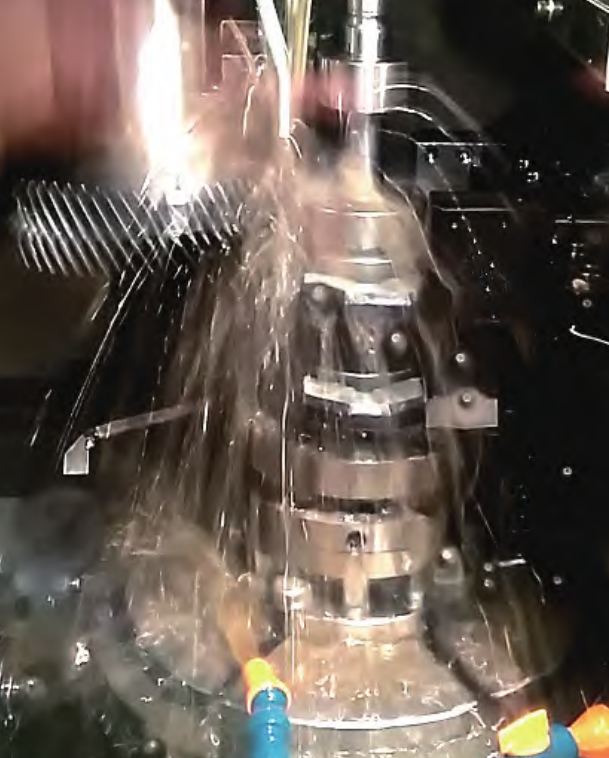
The rotating cutter head method is a commonly used and efficient cutting method for arc cylindrical gears. As shown in Figure 2 (insert the image of the rotating cutter head method cutting principle here), during the cutting process, there is an accurate generating motion relationship between the cutting cutter head and the gear blank. That is, the linear velocity of the pitch circle of the gear blank to be processed is equal to the linear velocity of the pitch line of the cutting cutter head. In addition to the main rotating motion, the cutting cutter head also has an inward – feed motion along the radial direction of the gear blank during the tooth cutting process of the arc gear. When using the generating method for processing, since only one tooth space can be cut at a time, after cutting each tooth space, the gear blank must be accurately indexed, and then the second tooth space can be cut. This process is repeated until all tooth spaces are cut, completing the processing of the arc gear.
However, although in theory, a double – edged cutter can cut out a complete tooth space at once, forming the convex and concave surfaces of the tooth, in practical applications, this method has some drawbacks. The double – edged cutter is fully engaged in cutting during the tooth – cutting process, resulting in a large cutting amount, rapid tool wear, and low – precision tooth surfaces. Therefore, it is difficult to cut arc gears that meet the requirements.
3.1.2 Single – Edge Cutter Cutting Method
Based on the practice of using double – edged cutters for tooth cutting, the single – edge cutter cutting method has been proposed. As shown in Figure 3 (insert the image of arc cylindrical gear cutting tools here, clearly showing the double – edged cutter and single – edge cutters with different radii), the single – edge cutter cutting method involves using single – edge cutters to separately finish – cut the convex and concave surfaces of the arc cylindrical gear. The advantage of this method is that the inner and outer single – edge cutters can be designed with equal radii, enabling higher – precision cutting of the convex and concave surfaces of the tooth. However, during the processing, issues such as gear blank installation and tool replacement need to be carefully considered, as any change in these aspects may affect the tooth – processing accuracy.
3.1.3 Single – Side Double – Milling Processing Method
To address the problems of tool replacement and gear blank installation in the single – edge cutter cutting method, the single – side double – milling processing method has been developed. The processing principle is illustrated in Figure 4 (insert the image of the single – side double – milling processing principle here). In this method, two workstations are designed on a special gear – milling machine to separately cut the convex and concave surfaces of the tooth. This method not only ensures the processing accuracy but also improves the processing efficiency to a certain extent. It is evident that the tooth – cutting processing of arc cylindrical gears requires dedicated CNC gear – milling equipment.
3.2 Tooth Surface Equation of Cutting Tools
During the milling process of arc cylindrical gears, special cutters are employed. To design and manufacture these special cutters, it is necessary to establish the tooth surface equation of the cutting tools based on the cutting processing principle of the rotating cutter head method. As shown in Figure 5 (insert the image of the coordinate systems of the cutter and the gear to be processed here), a coordinate system \([O_{1},x_{1},y_{1},z_{1}]\) is fixed on the gear blank to be processed, and a coordinate system \([O_{d},x_{d},y_{d},z_{d}]\) is associated with the milling cutter head. These two coordinate systems rotate with the gear blank and the milling cutter head respectively. A fixed coordinate system \([O,x,y,z]\) and an auxiliary coordinate system \([O_{1},x_{10},y_{10},z_{10}]\) are also established. If the pitch circle radius of the gear blank is \(R_{1}\) and the average radius of the milling cutter head is \(r_{0}\), the inner blade radius of the milling cutter is \(r_{0}-\frac{\pi m}{4}\), and the outer blade radius is \(r_{0}+\frac{\pi m}{4}\).
In the coordinate system \([O_{d},x_{d},y_{d},z_{d}]\) associated with the cutter, the parametric equation of the cutter surface can be established as follows: \( \begin{cases} x_{d}=( \pm u\sin\alpha_{1}+r_{0}\pm\frac{\pi}{4}m)\cos\theta\\ y_{d}=( \pm u\sin\alpha_{1}+r_{0}\pm\frac{\pi}{4}m)\sin\theta\\ z_{d}=u\cos\alpha_{1} \end{cases} \) where \(u\) represents the distance from a point along the generatrix of the conical surface to the reference point, and \(\theta\) is the rotation angle of the tool holder from the central section of the gear blank to the end face.
3.3 Cutting Process and Macro – Program Compilation
The cutting process of arc cylindrical gears can be divided into three steps:
- Use a three – edged tooth – space milling cutter to mill the tooth space in the middle of the tooth space of the arc cylindrical gear, removing most of the gear – blank material.
- Use a single – edge cutter to process the concave tooth surface.
- Use another single – edge cutter to process the convex tooth surface.
When processing on a special gear – milling machine, the indexing of the processing process can be programmed using both absolute indexing and relative indexing methods. For example, if the indexing angle of the gear according to the number of teeth is \(\delta\), the starting angle of the processing program for the first step is \(\frac{\delta}{2}\), that is, starting from the middle of the gear tooth space for rough – machining the tooth space. The second step starts from \(\delta = 0\), and the third step starts from \(\delta\). Two single – edge cutters are used to process the corresponding concave and convex tooth surfaces respectively. When each cutter completes the processing of the entire tooth space and tooth profile of the gear for one revolution, the processing of the entire arc cylindrical gear is completed. Since the cutter enters the workpiece along the involute profile, the cutter’s entry trajectory follows the involute curve.
4. Performance Testing and Evaluation of Arc Cylindrical Gears
4.1 Meshing Transmission Test
The meshing transmission test is a crucial means to evaluate the performance of arc cylindrical gears. In the test, the processed arc cylindrical gears are installed in a specific gear – transmission system. Key parameters such as the meshing accuracy, transmission stability, and noise level during the meshing process are measured. For example, advanced measuring instruments such as gear measuring centers can be used to accurately measure the tooth profile error, pitch error, and helix error of the gears. These errors directly affect the meshing accuracy of the gears. A smaller tooth profile error indicates that the actual tooth profile is closer to the theoretical involute profile, which is beneficial for improving the meshing performance of the gears.
During the meshing process, the transmission stability can be evaluated by observing the changes in the transmission ratio. A stable transmission ratio indicates that the gear meshing is smooth and there is no significant impact or vibration. Additionally, the noise level during gear meshing is an important indicator of the gear’s performance. High – precision gears with good meshing performance generally produce less noise during operation. By measuring the noise level at different rotational speeds and loads, the noise – reduction effect of the arc cylindrical gears can be comprehensively evaluated.
4.2 Influence of Processing Accuracy on Performance
The processing accuracy of arc cylindrical gears has a profound impact on their performance. High – precision processing can ensure that the actual geometric dimensions and tooth profiles of the gears are close to the theoretical values. For example, if the tooth profile error is too large, it will lead to uneven distribution of the meshing force between the teeth during the meshing process, resulting in increased wear and reduced service life of the gears. In severe cases, it may even cause tooth breakage.
The pitch error also affects the meshing performance of the gears. An inconsistent pitch between adjacent teeth can cause fluctuations in the transmission ratio during the meshing process, resulting in unstable transmission. Therefore, improving the processing accuracy of arc cylindrical gears is of great significance for enhancing their performance and reliability. This can be achieved through advanced processing
5. Comparison with Other Types of Gears
5.1 Comparison with Involute Spur Cylindrical Gears
Involute spur cylindrical gears are widely used in mechanical transmissions due to their simple design and relatively easy manufacturing process. However, as mentioned earlier, they have some inherent disadvantages. The sudden application and removal of loads along the entire tooth width during meshing lead to significant impact and noise, which limits their use in applications where smooth operation and low noise are required.
Arc cylindrical gears, on the other hand, have a more gradual meshing process. The engagement and disengagement of teeth occur in a sequential manner, reducing the impact and noise levels. In terms of load – bearing capacity, arc cylindrical gears generally have a higher ,which means that multiple pairs of teeth are in contact simultaneously during meshing. This results in a more even distribution of the load and a higher load – bearing capacity compared to involute spur cylindrical gears.
Another aspect to consider is the adaptability to installation errors. Involute spur cylindrical gears require a relatively high level of installation accuracy. Even a small deviation in the parallelism of the shafts can cause uneven tooth loading and accelerated wear. Arc cylindrical gears, with their arc – shaped tooth lines, can tolerate a certain degree of misalignment between the shafts without significantly affecting the meshing performance. This makes them more suitable for applications where the installation conditions are less than ideal.
The comparison is summarized in Table 2:
| Comparison Items | Involute Spur Cylindrical Gears | Arc Cylindrical Gears |
|---|---|---|
| Meshing Impact | Large, sudden load application and removal along the tooth width | Small, gradual meshing and unmeshing of teeth |
| Noise Level | High | Low |
| Load – Bearing Capacity | Relatively low due to single – pair – tooth meshing at a time (in most cases) | High, multiple – pair – tooth meshing increases load – bearing capacity |
| Adaptability to Installation Errors | Sensitive to shaft parallelism errors | Tolerant of small misalignments between shafts |
5.2 Comparison with Helical Cylindrical Gears
Helical cylindrical gears offer several advantages, such as large bearing capacity, high ,and smooth transmission. However, they also suffer from a major drawback – the presence of a significant axial force during operation. This axial force can put additional stress on the bearings and other components of the transmission system, requiring more robust and expensive bearing arrangements to support the shafts.
Arc cylindrical gears, while sharing some similarities with helical cylindrical gears in terms of load – bearing capacity and ,do not generate axial forces during meshing. This makes them an attractive alternative in applications where minimizing axial forces is crucial. For example, in high – speed and high – precision transmission systems, the elimination of axial forces can reduce wear and tear on the bearings, improve the overall efficiency of the system, and extend the service life of the components.
In terms of manufacturing complexity, helical cylindrical gears are relatively easier to manufacture compared to arc cylindrical gears. The cutting process for helical gears is well – established and can be carried out on standard gear – cutting machines. Arc cylindrical gears, on the other hand, require specialized cutting tools and equipment, which increases the manufacturing cost and complexity. However, with the continuous development of manufacturing technology, the cost – effectiveness of producing arc cylindrical gears is gradually improving.
The comparison is presented in Table 3:
| Comparison Items | Helical Cylindrical Gears | Arc Cylindrical Gears |
|---|---|---|
| Axial Force | Present, can be significant depending on the helix angle | Absent, no axial force during meshing |
| Load – Bearing Capacity | High | High |
| Noise Level | High | High |
| Manufacturing Complexity | Relatively simple, can be processed on standard machines | Complex, requires specialized tools and equipment |
| Application in High – Precision Systems | Limited by axial force – related issues | More suitable due to the absence of axial force |
6. Applications of Arc Cylindrical Gears
6.1 Aerospace Industry
In the aerospace industry, high – performance and reliable gear systems are essential for the operation of various aircraft components. Arc cylindrical gears, with their excellent transmission performance, are finding increasing applications in aircraft engines, landing gear systems, and flight control mechanisms.
In aircraft engines, where high – power transmission, high – speed rotation, and low weight are critical requirements, arc cylindrical gears can provide a more efficient and stable power – transfer solution. Their ability to handle high loads and reduce vibration and noise makes them ideal for use in the gearboxes that connect the engine’s components. For example, in a turbofan engine, the gearbox that transfers power from the turbine to the fan often uses arc cylindrical gears to ensure smooth and reliable operation at high rotational speeds.
In landing gear systems, arc cylindrical gears can be used in the actuation mechanisms that control the extension and retraction of the landing gear. The high load – bearing capacity and shock – resistance of these gears enable them to withstand the harsh forces experienced during landing and takeoff. Additionally, their tolerance to misalignment can help compensate for any small deviations in the installation of the landing gear components, improving the overall reliability of the system.
In flight control mechanisms, such as those that operate the ailerons, elevators, and rudders, arc cylindrical gears can provide accurate and responsive power transmission. The low noise and vibration levels associated with these gears are also important in maintaining the comfort and safety of the passengers and crew on board the aircraft.
6.2 Automotive Industry
The automotive industry is constantly seeking to improve the performance, efficiency, and durability of vehicles. Arc cylindrical gears have the potential to play a significant role in various automotive applications, including transmissions, differentials, and power – steering systems.
In automotive transmissions, arc cylindrical gears can offer several advantages over traditional gears. Their high and smooth meshing characteristics can lead to improved gear – shifting quality and reduced noise during operation. This is particularly important in modern high – performance vehicles and electric vehicles, where quiet and efficient operation is highly desirable. Additionally, the ability of arc cylindrical gears to tolerate misalignment can help simplify the design and assembly of the transmission system, reducing manufacturing costs.
In differentials, which are used to distribute power between the wheels of a vehicle while allowing them to rotate at different speeds, arc cylindrical gears can provide more reliable and efficient power transfer. The high load – bearing capacity of these gears enables them to handle the torque generated by the engine and transmit it to the wheels effectively. This can improve the traction and handling performance of the vehicle, especially in challenging driving conditions.
In power – steering systems, arc cylindrical gears can help reduce the effort required to steer the vehicle. Their smooth meshing and low friction characteristics can enhance the responsiveness and precision of the power – steering system, providing a better driving experience for the driver.
6.3 Heavy – Machinery Industry
In the heavy – machinery industry, such as in construction equipment, mining machinery, and industrial presses, high – load – bearing capacity and durability are crucial requirements for gear systems. Arc cylindrical gears are well – suited for these applications due to their robust design and excellent performance under heavy loads.
In construction equipment like bulldozers, excavators, and cranes, the gear systems are subjected to extremely high forces and torques. Arc cylindrical gears can withstand these heavy loads without significant wear or deformation, ensuring the reliable operation of the equipment. Their ability to handle shock loads is also important in these applications, as construction machinery often experiences sudden impacts during operation.
In mining machinery, such as conveyor belts, crushers, and hoists, arc cylindrical gears can provide efficient power transmission over long periods of time. The harsh operating environment in mines, including dust, moisture, and high temperatures, requires gears that are highly resistant to wear and corrosion. Arc cylindrical gears can be designed and manufactured using appropriate materials and surface treatments to meet these requirements.
In industrial presses, where large forces are applied to shape materials, arc cylindrical gears are used in the power – transmission systems to ensure accurate and stable operation. The high precision and low noise levels of these gears are also important in applications where the quality of the processed products is critical.
7. Challenges and Future Developments
7.1 Manufacturing – Related Challenges
One of the main challenges in the widespread adoption of arc cylindrical gears is the high cost associated with their manufacturing. The need for specialized cutting tools and equipment, as well as the complex manufacturing processes, contributes to the elevated production costs. This makes arc cylindrical gears less competitive compared to more commonly used gears in some price – sensitive markets.
Another manufacturing – related challenge is the difficulty in achieving high – precision machining. The unique tooth shape of arc cylindrical gears requires advanced machining techniques and high – precision machine tools to ensure that the actual tooth profile and dimensions meet the design requirements. Even small deviations in the machining process can have a significant impact on the performance and reliability of the gears.
7.2 Future Developments
To overcome the manufacturing challenges, ongoing research and development efforts are focused on improving the manufacturing processes of arc cylindrical gears. This includes the development of more advanced cutting tools and techniques that can reduce the manufacturing cost while maintaining or improving the machining precision. For example, the use of computer – aided design (CAD) and computer – aided manufacturing (CAM) technologies can optimize the cutting process and reduce the need for manual intervention, thereby improving the efficiency and accuracy of the manufacturing process.
In addition, the application of new materials in the manufacturing of arc cylindrical gears is also an area of active research. High – performance materials, such as advanced alloys and composite materials, can offer improved mechanical properties, such as higher strength, wear – resistance, and fatigue resistance. These materials can help extend the service life of the gears and improve their performance under harsh operating conditions.
Another future development trend is the integration of arc cylindrical gears with intelligent monitoring and control systems. By incorporating sensors and monitoring devices into the gear systems, it is possible to continuously monitor the operating conditions of the gears, such as temperature, vibration, and load. This information can be used to predict potential failures and schedule maintenance in a timely manner, improving the reliability and availability of the gear – driven systems.
8. Conclusion
Arc cylindrical gears represent a significant advancement in gear – design technology, offering unique advantages over traditional involute spur and helical cylindrical gears. Their excellent transmission performance, including high ,low noise, and absence of axial forces, makes them suitable for a wide range of applications in various industries, from aerospace and automotive to heavy – machinery.
However, the widespread adoption of arc cylindrical gears is currently limited by the challenges associated with their manufacturing, such as high costs and the need for specialized equipment. To fully realize the potential of arc cylindrical gears, continued research and development efforts are necessary to improve the manufacturing processes, develop new materials, and integrate intelligent monitoring systems.