1. Introduction
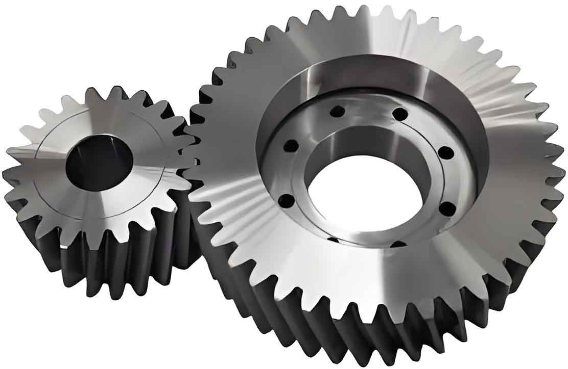
Cylindrical gears are fundamental components in mechanical transmission systems, responsible for transmitting torque and rotational motion between parallel shafts. Among various gear types, the variable hyperbolic circular arc tooth line cylindrical gear (VH-CATT) has gained attention due to its superior load-bearing capacity, high overlap ratio, and reduced axial thrust. However, the bending stress at the tooth root remains a critical factor affecting gear durability and performance. Previous studies have focused on machining methods, contact characteristics, and geometric modeling of VH-CATT gears, but the influence of design parameters—such as displacement coefficient, cutter head radius, module, tooth width, and cutter tip fillet radius—on bending stress remains underexplored.
This study aims to bridge this gap by deriving the tooth surface equations for VH-CATT gears, establishing a finite element analysis (FEA) model, and systematically evaluating how these parameters affect bending stress. The findings provide actionable insights for optimizing cylindrical gear design and enhancing operational reliability.

2. Theoretical Model of the Variable Hyperbolic Circular Arc Tooth Line Cylindrical Gear
2.1 Coordinate System Setup
The coordinate systems for machining VH-CATT gears include:
- Tool coordinate system O1−x1y1z1O1−x1y1z1: Fixed to the cutter head.
- Workpiece static coordinate system O2−x2y2z2O2−x2y2z2: Fixed to the gear blank.
- Workpiece dynamic coordinate system O3−x3y3z3O3−x3y3z3: Rotates with the gear.
The transformation matrices between these systems enable the derivation of tooth surface equations.
2.2 Tooth Surface Equations
The tooth surface of the cylindrical gear is derived using spatial meshing theory. The cutter head surface in O1O1 is expressed as:{x1=(R+π4msinα)cosθy1=(R+π4msinα)sinθz1=ucosα⎩⎨⎧x1=(R+4πmsinα)cosθy1=(R+4πmsinα)sinθz1=ucosα
where RR, mm, αα, and θθ represent cutter head radius, module, pressure angle, and angular parameter, respectively.
The meshing condition ϕ=n1⋅v2=0ϕ=n1⋅v2=0 governs the contact between the tool and workpiece. Solving this yields the contact line equation (Equation 6 in the PDF), which is transformed into the gear’s dynamic coordinate system to obtain the final tooth surface equations.
2.3 Transition Tooth Surface Equations
The transition surface near the tooth root is modeled by incorporating the cutter tip fillet radius rr:{xd=[A+r(cosα−cosβ)]cosθ+R+R1ψcosψyd=[A+r(cosα−cosβ)]cosθ−R1ψsinψzd=[A+r(cosα−cosβ)]sinθ⎩⎨⎧xd=[A+r(cosα−cosβ)]cosθ+R+R1ψcosψyd=[A+r(cosα−cosβ)]cosθ−R1ψsinψzd=[A+r(cosα−cosβ)]sinθ
Here, ββ depends on geometric parameters, ensuring smooth curvature transitions.
3. Finite Element Analysis Model
3.1 Model Setup
A 3D FEA model of a cylindrical gear pair was constructed using Abaqus. Key parameters are listed in Table 1.
Table 1: Design Parameters of the Cylindrical Gear Pair
| Parameter | Value | Parameter | Value |
|---|---|---|---|
| Pressure angle (αα) | 20° | Tip clearance coefficient | 0.25 |
| Module (mm) | 3 mm | Tooth width (BB) | 45 mm |
| Driving gear teeth (z1z1) | 21 | Cutter head radius (RR) | 80 mm |
| Driven gear teeth (z2z2) | 37 | Cutter tip fillet radius (rr) | 0.2 mm |
| Addendum coefficient | 1 |
3.2 Material Properties and Boundary Conditions
- Material: Elastic modulus = 210 GPa, Poisson’s ratio = 0.3.
- Mesh: Hexahedral reduced-integration elements (C3D8R).
- Boundary Conditions:
- Driving gear: Free rotation about its axis.
- Driven gear: Fixed rotation with 100 N·m torque applied.
4. Impact of Design Parameters on Bending Stress
4.1 Displacement Coefficient
The displacement coefficient (xx) significantly affects bending stress, increasing xx from -0.2 to 0.2 reduces stress in both driving and driven gears.
Table 2: Bending Stress vs. Displacement Coefficient
| Displacement Coefficient | Driving Gear Stress (MPa) | Driven Gear Stress (MPa) |
|---|---|---|
| -0.2 | 110.03 | 100.48 |
| -0.1 | 100.48 | 96.38 |
| 0 | 96.38 | 91.67 |
| 0.1 | 91.67 | 89.12 |
| 0.2 | 89.12 | 85.64 |
Key Insight: Positive displacement coefficients enhance bending strength by increasing tooth root thickness.
4.2 Cutter Head Radius
Larger cutter head radii (RR) reduce bending stress by expanding the load distribution area.
Table 3: Bending Stress vs. Cutter Head Radius
| Cutter Radius (mm) | Stress at x=0x=0 (MPa) |
|---|---|
| 60 | 112.4 |
| 80 | 96.4 |
| 100 | 84.7 |
4.3 Module
The module (mm) is a dominant factor. Increasing mm from 3 mm to 7 mm reduces stress by ~60–74%.
Table 4: Bending Stress Reduction with Module
| Module (mm) | Stress at x=0.2x=0.2 (MPa) | Reduction (%) |
|---|---|---|
| 3 | 89.12 | – |
| 5 | 24.7 | 72.3 |
| 7 | 22.64 | 60.0 |
4.4 Tooth Width
Tooth width (BB) initially lowers stress but plateaus beyond B=RB=R (45 mm in this case).
Table 5: Bending Stress vs. Tooth Width
| Tooth Width (mm) | Stress at x=0x=0 (MPa) |
|---|---|
| 30 | 106.49 |
| 45 | 96.38 |
| 60 | 95.10 |
4.5 Cutter Tip Fillet Radius
A larger fillet radius (rr) mitigates stress concentration but reduces overlap ratio beyond optimal values.
Table 6: Bending Stress vs. Fillet Radius
| Fillet Radius (mm) | Stress at x=0.2x=0.2 (MPa) |
|---|---|
| 0 | 94.05 |
| 0.2 | 89.12 |
| 0.4 | 88.90 |
5. Discussion
The analysis reveals that:
- Displacement Coefficient: Positive values enhance bending strength but require balancing with gear geometry constraints.
- Cutter Head Radius: Larger radii improve load distribution but increase manufacturing complexity.
- Module: Higher modules drastically reduce stress, favoring heavy-duty cylindrical gears.
- Tooth Width: Over-sizing BB wastes material without significant gains.
- Fillet Radius: Optimizing rr balances stress relief and overlap ratio.
6. Conclusion
This study systematically evaluates how design parameters influence bending stress in variable hyperbolic circular arc tooth line cylindrical gears. Key findings include:
- Positive displacement coefficients and larger modules significantly reduce stress.
- Cutter head radius and fillet radius require optimization to balance strength and manufacturability.
- Tooth width has limited impact beyond a critical threshold.
Future work will focus on multi-objective optimization algorithms to refine parameter selection for industrial applications.
