
1. Introduction
Gear systems play a crucial role in mechanical engineering, facilitating the transmission of power and motion across a wide range of applications. Among various gear types, arc cylindrical gears have gained significant attention due to their unique characteristics and advantages. This article aims to provide a detailed and comprehensive overview of arc cylindrical gears, covering their design principles, manufacturing methods, and practical applications. By the end of this article, readers will have a thorough understanding of arc cylindrical gears and their potential in mechanical systems.
2. Working Principle and Structure of Arc Cylindrical Gears
2.1 Working Principle
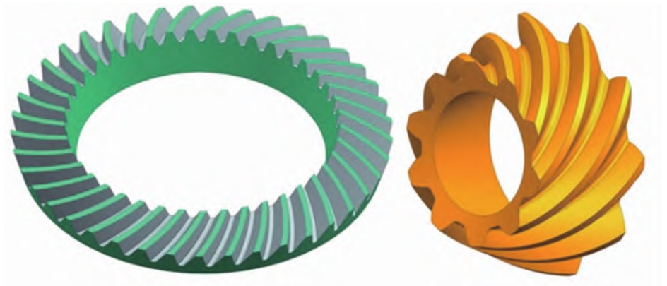
Arc cylindrical gears operate on the principle of meshing, where the teeth of two gears interact to transmit rotational motion. The key difference between arc cylindrical gears and other gear types, such as straight and helical gears, lies in the shape of their tooth profile. In arc cylindrical gears, the tooth profile is designed as an arc, which results in a unique meshing pattern.
During operation, the arc – shaped teeth of the gears come into contact gradually, reducing the impact and noise associated with gear meshing. This smooth engagement leads to a more stable and efficient power transmission. Additionally, the arc shape of the teeth allows for a larger contact area between the meshing gears, increasing the load – carrying capacity of the gear system.
2.2 Structure
The structure of arc cylindrical gears is characterized by their circular – arc – shaped tooth profile. The teeth are arranged along the circumference of the gear, with each tooth having a specific curvature. The basic components of an arc cylindrical gear include the gear body, teeth, and bore.
The gear body provides the structural support for the teeth and is typically made of a high – strength material, such as steel or alloy. The teeth are the functional parts of the gear, responsible for transmitting power through meshing. The bore is located at the center of the gear and is used to mount the gear on a shaft.
Table 1: Comparison of Key Structural Features of Different Gear Types
| Gear Type | Tooth Profile | Meshing Characteristics | Axial Load |
|---|---|---|---|
| Arc Cylindrical Gear | Circular – arc | Gradual meshing, low impact | Low |
| Straight Gear | Straight | Sudden meshing, high impact | None (ideally) |
| Helical Gear | Helical | Gradual meshing, medium impact | High |

3. Design of Arc Cylindrical Gears
3.1 Basic Parameters
The design of arc cylindrical gears involves several key parameters, which are essential for determining the gear’s performance and functionality. These parameters include:
- Modulus (m): The modulus is a fundamental parameter that defines the size of the gear teeth. It is calculated as the ratio of the pitch diameter to the number of teeth. A larger modulus indicates larger teeth, which can transmit more power.
- Number of Teeth (z): The number of teeth on a gear affects its speed ratio and torque transmission capabilities. The choice of the number of teeth is based on the specific requirements of the gear system, such as the desired speed reduction or increase.
- Pressure Angle (α): The pressure angle determines the direction of the force acting between the meshing teeth. In arc cylindrical gears, the pressure angle is typically chosen based on the application requirements, with common values ranging from 20° to 25°.
- Tooth Profile: The tooth profile of arc cylindrical gears is designed as an arc, which provides unique advantages in terms of meshing performance. The specific shape of the arc is determined by factors such as the gear’s application, load – carrying capacity, and manufacturing process.
Table 2: Common Values of Basic Parameters for Arc Cylindrical Gears
| Parameter | Symbol | Common Values |
|---|---|---|
| Modulus | m | 1 – 10 mm (depending on application) |
| Number of Teeth | z | 15 – 100 (varies based on speed ratio) |
| Pressure Angle | α | 20° – 25° |
3.2 Design Calculation
The design calculation of arc cylindrical gears is a complex process that involves several steps. The following is a general overview of the design calculation process:
- Determine the Design Requirements: The first step in the design process is to determine the specific requirements of the gear system, such as the power to be transmitted, the speed ratio, and the operating conditions.
- Select the Gear Material: The choice of gear material is crucial for ensuring the gear’s performance and durability. Common gear materials include steel, alloy steel, and non – ferrous metals. The material selection is based on factors such as the gear’s application, load – carrying capacity, and cost.
- Calculate the Basic Parameters: Once the design requirements and gear material have been determined, the next step is to calculate the basic parameters of the gear, such as the modulus, number of teeth, and pressure angle. These parameters are calculated using formulas based on the gear design principles.
- Determine the Gear Dimensions: After calculating the basic parameters, the next step is to determine the dimensions of the gear, such as the pitch diameter, tooth width, and addendum. These dimensions are calculated based on the basic parameters and the gear design standards.
- Check the Gear Strength: The final step in the design process is to check the strength of the gear to ensure that it can withstand the expected loads. The gear strength is checked using formulas based on the gear material and the design parameters.
Table 3: Design Calculation Formulas for Arc Cylindrical Gears
| Parameter | Formula |
|---|---|
| Pitch Diameter (d) | d = mz |
| Tooth Width (b) | b = (6 – 10)m (typical range) |
| Addendum (ha) | ha = m |
| Dedendum (hf) | hf = 1.25m |
4. Manufacturing of Arc Cylindrical Gears
4.1 Cutting Methods
The manufacturing of arc cylindrical gears involves several processes, with cutting being one of the most critical. The following are the common cutting methods used for manufacturing arc cylindrical gears:
- Rotating Cutter Head Method: This is a widely used method for cutting arc cylindrical gears. In this method, a rotating cutter head is used to cut the gear teeth. The cutter head is designed with a specific shape and geometry to match the tooth profile of the arc cylindrical gear. The gear blank is rotated while the cutter head moves along the gear blank’s axis to cut the teeth.
- Parallel Linkage Method: The parallel linkage method is another cutting method used for manufacturing arc cylindrical gears. In this method, a parallel linkage mechanism is used to control the movement of the cutting tool. The gear blank is fixed, and the cutting tool moves along a specific path to cut the teeth. This method is less commonly used than the rotating cutter head method due to its complexity and higher cost.
Table 4: Comparison of Cutting Methods for Arc Cylindrical Gears
| Cutting Method | Advantages | Disadvantages |
|---|---|---|
| Rotating Cutter Head Method | High efficiency, easy to implement | Requires specialized cutter heads |
| Parallel Linkage Method | Precise control of cutting path | Complex mechanism, high cost |

4.2 Cutting Tools
The choice of cutting tools is crucial for the quality and efficiency of the gear manufacturing process. The following are the common cutting tools used for manufacturing arc cylindrical gears:
- Single – Edge Cutters: Single – edge cutters are commonly used for cutting the convex and concave surfaces of arc cylindrical gear teeth. These cutters are designed with a single cutting edge, which allows for precise control of the cutting process.
- Double – Edge Cutters: Double – edge cutters can be used for rough cutting of the gear teeth. However, due to the large cutting force and high tool wear, they are often not suitable for finishing cuts.
Table 5: Comparison of Cutting Tools for Arc Cylindrical Gears
| Cutting Tool | Application | Advantages | Disadvantages |
|---|---|---|---|
| Single – Edge Cutter | Finishing cuts | High precision | Low cutting speed |
| Double – Edge Cutter | Rough cutting | High cutting speed | High tool wear |
4.3 NC Machining Program
In modern gear manufacturing, numerical control (NC) machining is widely used to improve the accuracy and efficiency of the manufacturing process. The NC machining program for arc cylindrical gears is developed based on the gear design parameters and the cutting method.
The NC machining program controls the movement of the cutting tool and the rotation of the gear blank to ensure that the gear teeth are cut with the required accuracy. The program also includes instructions for tool changes, feed rates, and spindle speeds.
Table 6: Key Steps in NC Machining Program for Arc Cylindrical Gears
| Step | Description |
|---|---|
| 1 | Define the gear design parameters |
| 2 | Select the cutting method and tools |
| 3 | Generate the tool path |
| 4 | Program the feed rates and spindle speeds |
| 5 | Test and optimize the program |
5. Application of Arc Cylindrical Gears
5.1 Industrial Machinery
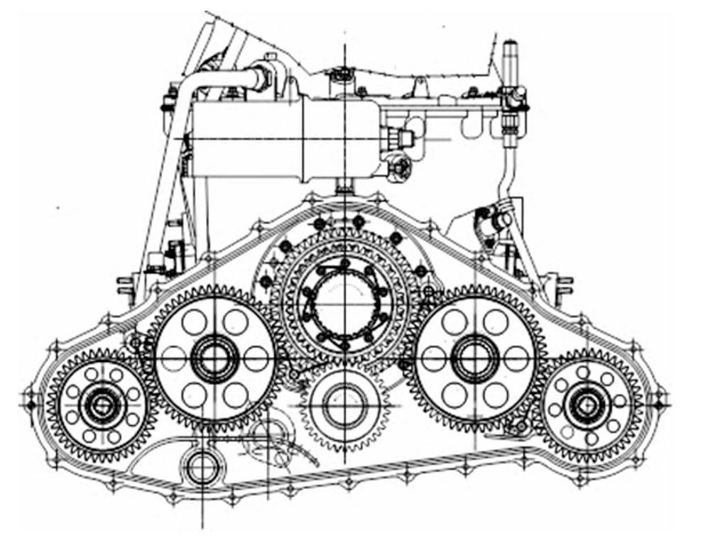
Arc cylindrical gears are widely used in various industrial machinery applications, such as:
- Mining Equipment: In mining equipment, arc cylindrical gears are used to transmit power and motion in crushers, conveyors, and mills. The high load – carrying capacity and smooth operation of arc cylindrical gears make them suitable for these heavy – duty applications.
- Machine Tools: Arc cylindrical gears are used in machine tools to provide precise motion control and power transmission. The low noise and vibration levels of arc cylindrical gears are particularly important in machine tool applications, where accuracy is crucial.
Table 7: Application of Arc Cylindrical Gears in Industrial Machinery
| Industrial Machinery | Function of Arc Cylindrical Gears |
|---|---|
| Mining Equipment | Transmit power in heavy – duty operations |
| Machine Tools | Provide precise motion control |

5.2 Automotive Industry
In the automotive industry, arc cylindrical gears are used in various applications, including:
- Transmissions: Arc cylindrical gears are used in automotive transmissions to provide smooth and efficient power transfer between the engine and the wheels. The high torque – carrying capacity and low noise levels of arc cylindrical gears make them ideal for this application.
- Differentials: Differentials in automotive drivetrains use arc cylindrical gears to distribute power between the wheels while allowing for different rotational speeds. The unique meshing characteristics of arc cylindrical gears ensure smooth operation and efficient power transfer in different driving conditions.
Table 8: Application of Arc Cylindrical Gears in the Automotive Industry
| Automotive Component | Function of Arc Cylindrical Gears |
|---|---|
| Transmissions | Provide smooth power transfer |
| Differentials | Distribute power between wheels |
6. Advantages and Disadvantages of Arc Cylindrical Gears
6.1 Advantages
- High Load – Carrying Capacity: The arc – shaped tooth profile of arc cylindrical gears provides a larger contact area between the meshing teeth, resulting in a higher load – carrying capacity compared to other gear types.
- Smooth Operation: The gradual meshing of arc cylindrical gear teeth reduces impact and noise, leading to smooth operation and reduced vibration levels.
- Good Adaptability to Misalignment: Arc cylindrical gears can tolerate a certain degree of misalignment between the shafts, making them suitable for applications where precise alignment is difficult to achieve.
Table 9: Comparison of Advantages of Arc Cylindrical Gears with Other Gear Types
| Gear Type | Load – Carrying Capacity | Smooth Operation | Adaptability to Misalignment |
|---|---|---|---|
| Arc Cylindrical Gear | High | Excellent | Good |
| Straight Gear | Low | Poor | Poor |
| Helical Gear | Medium | Good | Medium |
6.2 Disadvantages
- Complex Manufacturing Process: The manufacturing of arc cylindrical gears requires specialized equipment and cutting tools, which increases the complexity and cost of the manufacturing process.
- High Cost: Due to the complex manufacturing process and the need for specialized equipment, arc cylindrical gears are generally more expensive than other gear types.
Table 10: Comparison of Disadvantages of Arc Cylindrical Gears with Other Gear Types
| Gear Type | Manufacturing Complexity | Cost |
|---|---|---|
| Arc Cylindrical Gear | High | High |
| Straight Gear | Low | Low |
| Helical Gear | Medium | Medium |
7. Future Trends in Arc Cylindrical Gear Technology
7.1 Advanced Manufacturing Techniques
The future of arc cylindrical gear manufacturing is likely to involve the use of advanced manufacturing techniques, such as:
- Additive Manufacturing: Additive manufacturing, also known as 3D printing, has the potential to revolutionize the gear manufacturing process. This technique allows for the production of complex gear geometries with high precision, reducing the need for traditional machining processes.
- Advanced CNC Machining: Continued advancements in computer – numerical – control (CNC) machining technology will lead to more precise and efficient gear manufacturing. Advanced CNC machines can be programmed to produce gears with complex tooth profiles and tight tolerances.
7.2 Material Innovations
The development of new materials will also play a significant role in the future of arc cylindrical gear technology. New materials with improved mechanical properties, such as high strength – to – weight ratios and better wear resistance, will be developed to enhance the performance and durability of arc cylindrical gears.
8. Conclusion
Arc cylindrical gears offer unique advantages in terms of load – carrying capacity, smooth operation, and adaptability to misalignment. However, their complex manufacturing process and high cost limit their widespread application in some industries. With the development of advanced manufacturing techniques and material innovations, the future of arc cylindrical gear technology looks promising. By understanding the design, manufacturing, and application of arc cylindrical gears, engineers can make informed decisions when selecting gear systems for their specific applications, leading to more efficient and reliable mechanical systems.