1. Introduction
1.1 Research Background and Significance
Gears are crucial components in transmission systems, widely used in various industries such as aerospace, construction machinery, medical devices, and marine vessels. Internal gears, in particular, play an irreplaceable role in important structures like automotive reducers and gearboxes. As the demand for high – quality gears increases, the requirements for gear processing accuracy are also rising.
Traditional gear processing methods, including hobbing, shaping, and grinding, have limitations. For example, shaping has low processing efficiency due to its empty stroke during the return movement, grinding is costly, and broaching requires expensive equipment and has environmental pollution problems. In contrast, gear skiving has emerged as a promising alternative. It combines the advantages of hobbing and shaping, featuring high processing efficiency, flexibility, high – precision workpiece production, and long tool life. It has become a mainstream gear processing method in recent years, especially for internal gear processing.
The design of the gear skiving tool is a key technology in gear machining, which directly affects the tool life and gear processing accuracy. Therefore, researching the profile design and manufacturing of gear skiving tools for spur internal gear machining is of great significance for improving gear quality and reducing production costs.
1.2 国内外研究现状(Research Status at Home and Abroad)
1.2.1 Research Status of Gear Skiving Processing Methods
Gear skiving, also known as 剐齿,刮齿,or 滚插齿加工 in Chinese, and Skiving, Power skiving, Scudding in foreign literature, is a relatively new processing technology. It was first patented by William. Pittler von in 1910. This technology combines the characteristics of traditional gear shaping and hobbing. However, due to the high – requirements for equipment stiffness and synchronous movement of tools and workpieces at that time, it experienced a 50 – year dormancy period.
In the 1960s, the Soviet Union’s All – Union Tool Research Institute began to study the rough – turning processing method of spur and helical gears using gear skiving tools with a back angle. Volker Schulze and others believe that gear skiving is a continuous rolling gear cutting method, which is a perfect combination of hobbing and shaping, with high productivity and flexibility.
In China, Jin Jing and others were the first to study gear skiving. They pointed out that the structure of the gear skiving tool is basically the same as that of the shaping tool, and the cutting motion is the same as that of hobbing, but the installation position is different. Hunan University, in collaboration with Luoyang First Tractor Factory, proposed the principle of gear skiving forming for curves and surfaces and studied the design of Archimedes worm straight – tooth gear skiving tools.
| Researcher/Institution | Research Content |
|---|---|
| William. Pittler von | Patented gear skiving technology in 1910 |
| Soviet Union’s All – Union Tool Research Institute | Studied rough – turning processing of spur and helical gears with gear skiving tools in the 1960s |
| Volker Schulze | Considered gear skiving as a continuous rolling gear cutting method |
| Jin Jing | Studied the basic principles of gear skiving in China |
| Hunan University & Luoyang First Tractor Factory | Proposed the principle of gear skiving forming for curves and surfaces |
1.2.2 Structural Design Improvements of Gear Skiving Processing
In the field of machine tool design and manufacturing, German company Profilator GmbH & Co. KG developed the S240 – R gear skiving machine in 2006, and Changsha Machine Tool Co., Ltd. in China developed the YK1015A slicing machine in 2010. The American Gleason Company designed and developed the 600PS power gear skiving machine in 2013, which is in a leading position in the gear tool design and research field.
Regarding the gear skiving tool structure, Fritz Klocke and others analyzed the influencing factors of tool wear through cutting experiments. Tianjin University’s Li Jia, Chen Xinchun and their team proposed a design method for gear skiving tools without theoretical edge – shape errors. Jiangsu University’s Guo Erkuo and his team studied the error compensation method during gear skiving processing and designed multi – blade gear skiving tools.
| Company/Researcher | Research Content |
|---|---|
| Profilator GmbH & Co. KG | Developed the S240 – R gear skiving machine in 2006 |
| Changsha Machine Tool Co., Ltd. | Developed the YK1015A slicing machine in 2010 |
| Gleason Company | Developed the 600PS power gear skiving machine in 2013 |
| Fritz Klocke | Analyzed tool wear factors |
| Li Jia, Chen Xinchun (Tianjin University) | Proposed a design method for gear skiving tools without theoretical edge – shape errors |
| Guo Erkuo (Jiangsu University) | Studied error compensation methods and designed multi – blade gear skiving tools |
1.2.3 Research Status of Gear Skiving Cutting Simulation
Simulation analysis before actual gear skiving processing can predict the stability of the processing process, reduce time consumption, and lower production costs. Dr. H.J. Stadtfeld introduced the cutting process and chip formation process of gear skiving tools. Angelos Marinakis and others designed a simulation software to predict chip shape and cutting force. Nikolaos Tapoglou proposed a model to predict cutting force during gear skiving processing.
| Researcher | Research Content |
|---|---|
| Dr. H.J. Stadtfeld | Introduced the cutting and chip formation process of gear skiving tools |
| Angelos Marinakis | Designed simulation software for predicting chip shape and cutting force |
| Nikolaos Tapoglou | Proposed a model for predicting cutting force in gear skiving processing |
1.3 Existing Problems in Current Research
Although significant progress has been made in gear skiving technology research, there are still some problems. Research on the influence of the number of envelope passes during gear skiving of internal gears on gear tooth profile deviation is scarce. The research on the influence of the profile shift coefficient of gear skiving tools on gear tooth profile accuracy deviation is also insufficient. In addition, the impact of gear skiving tool tooth surface modification on tool life and gear tooth surface accuracy has not been thoroughly studied.
1.4 Main Research Contents of This Article
This article aims to improve the tooth profile accuracy of spur internal gears processed by gear skiving. Based on the gear skiving processing principle and gear meshing principle, research is carried out on the velocity change at the meshing point, the envelope forming of the internal gear tooth profile, the selection of the profile shift coefficient of the gear skiving tool, and the tooth surface modification of the gear skiving tool.
The specific research contents include establishing a mathematical model of the internal gear skiving process, analyzing the velocity at the meshing point, studying the envelope forming of the gear tooth surface, determining the range of the profile shift coefficient of the gear skiving tool, analyzing the influence of the axis – intersection angle error on the gear tooth profile deviation, designing and analyzing the tooth surface modification of the gear skiving tool, and conducting simulation analysis and experimental verification of gear skiving processing.
2. Meshing Velocity and Internal Gear Tooth Surface Envelope Analysis Based on Gear Skiving Processing Principle
2.1 Gear Skiving Processing Principle
Gear skiving can be regarded as a processing method where one gear in a pair of helical meshing gear pairs (either disc – shaped or gear – shaped) is used as a tool, and the other is used as a workpiece, with the tool or workpiece moving axially along the workpiece. In the gear skiving cutting process, the axes of the gear skiving tool and the workpiece are skewed and cross – formed at a certain angle, called the axis – intersection angle Σ. This angle ensures that the workpiece and the gear skiving tool maintain a spiral – line tangency state on the pitch cylinder, making gear skiving a spatial meshing processing method.
The cutting process of the gear skiving tool requires multiple motions. The gear skiving tool and the gear blank need to rotate synchronously at a certain speed ratio to complete the meshing motion, and the gear skiving tool or the gear also needs to move axially to ensure that the entire tooth width of the gear is processed. The main motion is the constant – speed rotation of the workpiece around its axis, and the sub – motion is the constant – speed rotation of the gear skiving tool around its axis.
Gear skiving can process both external and internal gears, as well as spur and helical gears. In terms of tool use, spur gears are processed with helical gear skiving tools, and both straight – tooth and helical – tooth gear skiving tools can process helical gears. The gear skiving tool has two structural forms: taper – shank and bowl – type, similar to the shaping tool.
[Insert a diagram here to illustrate the gear skiving processing principle, showing the relative positions of the gear skiving tool and the workpiece, and the axis – intersection angle]
2.2 Analysis of Motion Velocity at the Meshing Point
The actual cutting speed varies significantly along the cutting edge, and it mainly comes from the synchronous rotation of the workpiece and the gear skiving tool. To accurately describe the cutting speed, a series of vector operations are required.
Let the angular velocity of the gear skiving tool be \(\omega^{1}=\omega_{1}k\) and its axial movement speed be \(v^{1}\), and the angular velocity of the workpiece be \(\omega^{2}=\omega_{2}\cos\sum j-\omega_{2}\sin\sum k\). The relative motion velocity \(V^{M}\) at the meshing point M between the gear skiving tool and the workpiece is related to the radii, rotation speeds, and feed speeds of the two.
In the gear skiving process, the cutting speed at the contact point between the workpiece and the gear skiving tool is affected by the rotation speeds of the gear skiving tool \(\omega_{1}\) and the workpiece \(\omega_{2}\), as well as the axis – intersection angle \(\sum\). If the angular velocities of the gear skiving tool and the workpiece spindle can be accurately controlled, precise processing can be achieved without feed motion. However, in actual processing, due to the existence of axial feed motion and the axis – intersection angle, an additional rotation speed needs to be added to the gear skiving tool to ensure correct meshing.
| Parameter | Formula |
|---|---|
| Angular velocity of gear skiving tool | \(\omega^{1}=\omega_{1}k\) |
| Angular velocity of workpiece | \(\omega^{2}=\omega_{2}\cos\sum j-\omega_{2}\sin\sum k\) |
| Relative motion velocity at meshing point M | \(V^{M}=\omega^{1}×r^{1}+v^{1}-\omega^{2}×r^{2}\) |
2.3 Envelope Forming of Gear Tooth Surface in Gear Skiving Processing
During the gear skiving process, the cutting thickness, working rake angle, back angle, and edge inclination angle of the gear skiving tool are constantly changing. Due to the existence of the back angle, the gear skiving tool is equivalent to a profile – shifted gear in structure. When processing a gear with a gear skiving tool, it is equivalent to the meshing of profile – shifted gears with unequal profile – shift amounts, which belongs to angular profile – shifting.
Based on the conjugate meshing principle, when one tooth surface moves, it will sweep out multiple surfaces to form a surface family. The gear processing process is a process of envelope forming. By establishing coordinate transformation formulas and using software simulation, the tooth profile of the internal gear can be enveloped.
The simulation results show that the number of envelope passes is related to the tooth profile accuracy of the gear. The more the number of envelope passes, the higher the tooth profile accuracy. In the simulation, when the number of envelope passes increases from 10 to 73, the tooth profile at the tooth tip becomes smoother, and the tooth profile accuracy improves.
[Insert a graph here to show the relationship between the number of envelope passes and gear tooth profile accuracy, with the number of envelope passes on the x – axis and tooth profile accuracy on the y – axis]
2.4 Chapter Summary
This chapter established the coordinate relationship diagram of the gear skiving tool and the internal gear during gear skiving processing based on the gear skiving principle. The relative motion velocity at any meshing point was obtained, and the decomposition velocities of axial feed and radial feed at the meshing point were analyzed. Through software simulation, the tooth profile of the internal gear was enveloped. It was found that within the processing accuracy range, the more the number of envelope passes, the smaller the gear tooth profile deviation, and the higher the accuracy.
3. Influence of Gear Skiving Tool Profile Shift Coefficient and Axis – Intersection Angle Error on Gear Tooth Profile Deviation
3.1 Introduction to the Selection Principle of Gear Skiving Tool Profile Shift Coefficient
The gear skiving tool is a profile – shifted gear in structure, and the profile shift coefficient is an important parameter in its design. The profile shift coefficient decreases with the increase of the number of grinding times. When selecting the profile shift coefficient of the gear skiving tool, the maximum value within the allowable range is usually adopted to ensure that after multiple uses and grindings, the profile shift coefficient of the old gear skiving tool can reach the expected minimum value.
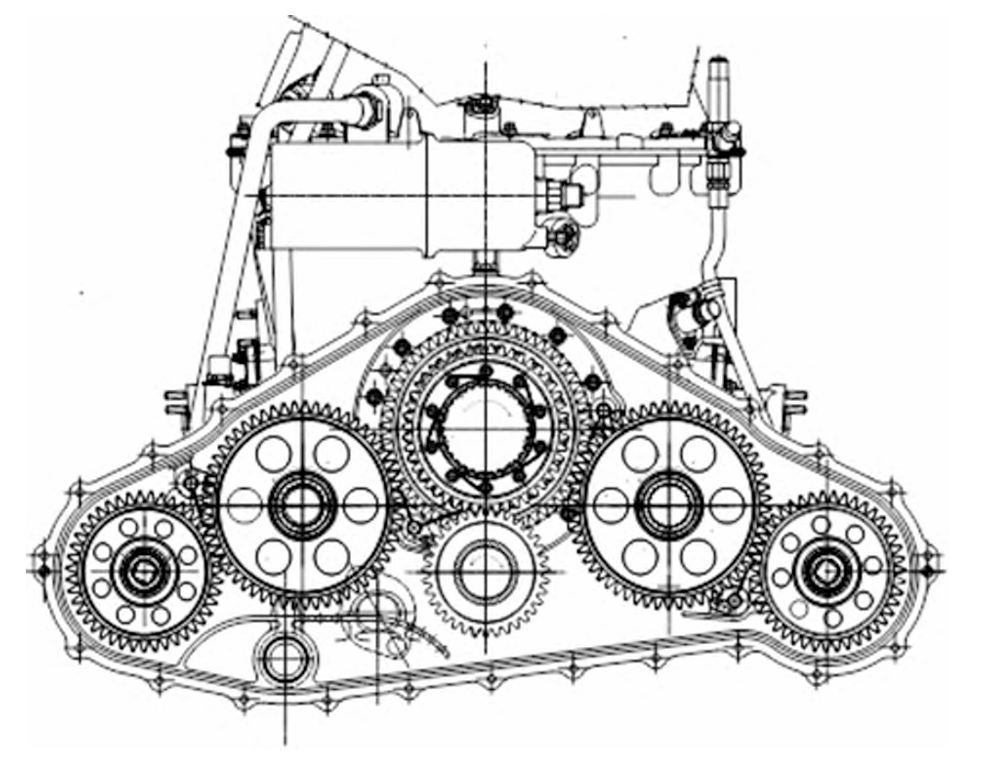
The limit value of the profile shift coefficient of the gear skiving tool is restricted by many factors. In this chapter, the parameters of the internal gear are based on the data provided by a certain motor reduction housing drawing, and the optimal value of the profile shift coefficient of the gear skiving tool for this internal gear is designed.
3.2 Calculation Method of Gear Profile Shift Coefficient
When designing a gear skiving tool according to gear parameters, the gear profile shift coefficient can be obtained in different ways. Some drawings directly provide the gear profile shift coefficient, while for those providing the measurement of the span – rod distance or the number of teeth across, the gear profile shift coefficient can be calculated through formulas. The most commonly used method is to calculate through the measurement of the number of teeth across and the span – rod distance. In addition, software like Kisssoft can also automatically calculate the profile shift coefficient.
3.3 Selection of Gear Skiving Tool Profile Shift Coefficient and Its Influence on Gear Tooth Profile
3.3.1 Influence of the Maximum Profile Shift Coefficient of the Gear Skiving Tool on the Gear Tooth Profile
The selection of the maximum profile shift coefficient of the gear skiving tool needs to consider factors such as the limitation of negative meshing angles, the sharpening of the gear skiving tool tooth tip, and the undercutting of the gear during processing.
The relationship between the profile shift coefficient and the meshing angle shows that the larger the profile shift coefficient of the gear skiving tool, the more likely a negative meshing angle will occur, which will prevent the smooth progress of gear skiving processing. The relationship between the profile shift coefficient and the tooth tip width of the gear skiving tool indicates that an overly large profile shift coefficient will cause the tooth tip of the gear skiving tool to become sharp, affecting chip removal and tool durability.
3.3.2 Influence of the Minimum Profile Shift Coefficient of the Gear Skiving Tool on the Gear Tooth Profile
The minimum profile shift coefficient of the gear skiving tool is related to the occurrence of undercutting. When the number of teeth difference between the internal gear and the gear skiving tool is small, undercutting may occur. To avoid undercutting, the minimum profile shift coefficient of the internal gear skiving tool needs to be restricted.
The influencing factors of the minimum profile shift coefficient include the gear profile shift coefficient, the meshing angle, the number of teeth difference between the gear and the gear skiving tool, and the pressure angle. By comprehensively considering these factors, the range of the profile shift coefficient of the gear skiving tool can be determined. For a specific internal gear with a gear profile shift coefficient of – 0.25 and 83 teeth, considering avoiding local wear of the gear skiving tool, the number of teeth of the gear skiving tool is taken as 37, and the range of the profile shift coefficient of the gear skiving tool is (0, 0.34).
| Influence Factor | Relationship with Profile Shift Coefficient |
|---|---|
| Meshing angle | The larger the meshing angle, the smaller the minimum profile shift coefficient |
| Gear profile shift coefficient | The larger the gear profile shift coefficient, the larger the minimum profile shift coefficient |
3.4 Relationship between Gear Skiving Tool Profile Shift Coefficient and Gear Tooth Profile Deviation
Taking DIN 7 – level accuracy as the standard and setting the number of envelope passes to 73, the relationship between the profile shift coefficient of the gear skiving tool and the tooth profile deviation was studied. The results show that within the obtained profile shift coefficient range, the smaller the profile shift coefficient of the gear skiving tool, the smaller the enveloped gear tooth profile deviation, and the higher the gear accuracy. When the tooth profile deviation is 0.003 mm, the optimal profile shift coefficient \(x_{1}\) of the gear skiving tool is 0.29.
3.5 Influence of Axis – Intersection Angle Error on Gear Skiving Processing
The axis – intersection angle error has an important impact on the tooth profile accuracy of the workpiece. In actual gear skiving processing, the axis – intersection angle is controlled by the worm – gear drive, but the transmission error of the servo – motor can lead to the hysteresis of the worm – gear drive, resulting in an axis – intersection angle error.
The axis – intersection angle error can cause over – cutting or under – cutting of the gear tooth profile. By establishing the relationship between the axis – intersection angle error and the tooth profile deviation formula and conducting Matlab simulation, it is found that as the axis – intersection angle error increases, the tooth profile deviation of the internal gear gradually increases. However, within the allowable range of the machine tool, increasing the rotational speed or the feed speed of the gear skiving tool can suppress the influence of the axis – intersection angle error on the gear tooth profile deviation.
| Influence Factor | Impact on Tooth Profile Deviation |
|---|---|
| Axis – intersection angle error | Increases tooth profile deviation |
| Rotational speed/Feed speed | Suppresses the influence of axis – intersection angle error on tooth profile deviation |
3.6 Chapter Summary
This chapter studied the range of the profile shift coefficient of the gear skiving tool from the aspects of the profile shift coefficient of the gear skiving tool and the axis – intersection angle error. By setting the same number of envelope passes and comparing the envelope accuracy differences under different profile shift coefficients, the optimal profile shift coefficient of the internal gear skiving tool was determined. It was found that the smaller the profile shift coefficient of the gear skiving tool, the higher the accuracy of the internal gear tooth surface obtained by envelope. Through simulation analysis, it was shown that increasing the relative rotational speed of the gear skiving tool or the gear blank and the axial feed speed of the gear skiving tool can suppress the influence of the axis – intersection angle error on the internal gear tooth profile deviation, thereby improving the internal gear tooth profile accuracy.
4. Tooth Surface Modification Design and Analysis of Gear Skiving Tool
4.1 Purpose of Modification
The tooth shape error of the gear skiving tool will be transferred to the gear profile during the processing, reducing the shape accuracy of the gear. Modifying the gear skiving tool is an important way to reduce the meshing transmission error, improve the strength of the gear skiving tool, and reduce the gear tooth shape deviation.
The errors in gear processing can be divided into two major parts: the original errors of the process system and the errors in the process. The gear skiving tool’s structure, tooth surface shape, and material properties have a significant impact on the accuracy and quality of the gear. The tooth surface structure error of the tool determines the gear forming error to a certain extent.
The purpose of gear skiving tool modification is to improve the tooth surface accuracy of the gear and the strength and life of the gear skiving tool, which is different from the purpose of gear modification. Gear modification is mainly to reduce noise, vibration, and prevent undercutting during the meshing process.
4.2 Tooth Surface Modification Methods
Common modification methods include profile modification, lead modification, and diagonal modification. Profile modification is to remove a small amount of material along the involute direction for micro – trimming, making it deviate from the theoretical tooth profile, usually only modifying the tooth tip and tooth root. Lead modification is to perform micro – trimming along the tooth width direction, making it deviate from the theoretical tooth surface. Diagonal modification is a three – dimensional modification method mainly used for helical gears, with modification amounts changing along the tooth profile and tooth width directions.
Since there is no specific manual and formula for gear skiving tool modification, and the gear skiving tool is a profile – shifted gear in structure, the modification amounts of different modification methods are initially calculated according to the gear modification formula. In this chapter, the gear skiving tool tooth tip, tooth root, and tooth profile are modified by involute modification, lead crowning modification, and diagonal modification.
| Modification Method | Modification Location | Modification Principle |
|---|---|---|
| Involute modification | Tooth tip and tooth root | Remove material along the involute direction |
| Lead crowning modification | Along the tooth width | Make the tooth shape convex in the middle |
| Diagonal modification | Tooth profile and tooth width (for helical gears) | Modification amounts change in three – dimensional directions |
4.3 Meshing Simulation of Gear Skiving Tool Modification
Due to the existence of the axis – intersection angle in gear skiving processing, there is currently no publicly available modification simulation analysis software. In this paper, the small gear in a pair of meshing gears is regarded as a gear skiving tool for modification simulation design.
When selecting modification parameters, the influence of gear skiving tool tooth surface modification on the transmission error amplitude, tooth root bending stress, and tooth surface stress distribution should be considered to improve the meshing performance. The feasibility of the modification scheme is judged based on the meshing transmission error value, load force size change, and contact spot position change before and after the modification of the gear skiving tool tooth surface.
4.3.1 Transmission Error Analysis
Transmission error is the deviation between the actual and ideal meshing positions of the driven wheel’s tooth profile along the meshing line. It is usually expressed by angle error, and the formula is \(TE = (\theta_{2}+\Delta\theta_{2})×r_{b2}-\theta_{1}r_{b1}\). Transmission error and contact state are used to describe the transmission performance of the meshing pair.
In the ideal processing state without various errors, the transmission errors before and after the modification of the gear skiving tool were analyzed. The results show that after modification, the absolute peak value of the transmission error decreases, and the transmission error curve becomes relatively gentle, indicating that the dynamic performance of the gear skiving tool during the gear processing transmission is improved. Among the different modification schemes, schemes d, e, and f have better modification effects.
[Insert a graph here to show the transmission error curves before and after modification, with the rotation angle of the gear skiving tool on the x – axis and the transmission error on the y – axis]
4.3.2 Force Analysis
The load distribution on the meshing tooth surface of the gear skiving tool is affected by many factors, such as manufacturing errors, installation errors, and transmission errors during processing. By comparing the force analysis of the gear skiving tool tooth surface before and after modification under ideal working conditions, it can be seen that the unmodified gear skiving tool tooth surface shows obvious force – concentration and off – load phenomena, while after modification, the position and size of the contact spot on the tooth surface change, and the uneven load distribution along the tooth width direction is improved.
Schemes e and f are considered ideal results as they can reduce the tooth surface force and improve the load distribution, enhancing the tooth surface strength of the gear skiving tool.
| Modification Scheme | Maximum Unit – Length Load (N/mm) | Maximum Contact Stress (MPa) | Load Distribution |
|---|---|---|---|
| Unmodified a | 122.9 | 487 | Left – side off – load |
| Modified b | 126.2 | 487 | Slightly improved left – side off – load |
| Modified c | 117.2 | 468 | Both – ends large, middle – small load distribution |
| Modified d | 141 | 511 | Middle – part stress concentration |
| Modified e | 119 | 472 | Relatively uniform left – side distribution |
| Modified f | 109.9 | 451 | Symmetric stress distribution |
4.3.3 Meshing Force Trajectory Analysis
During the gear skiving process, due to the axis – intersection angle and the three – linkage processing method, the meshing force of the gear skiving tool and the workpiece’s teeth is different at different rotation angles in each tooth cycle. After modification, the meshing force difference decreases, which is beneficial to reducing vibration during meshing and improving the manufacturing accuracy of the gear.
By comparing the meshing force trajectories of different modification schemes, it is found that the involute modification can expand the off – load concentration range, the lead crowning modification can shift the meshing force concentration point to the middle of the tooth surface, and the diagonal modification makes the tooth surface have off – load at both ends. Therefore, the diagonal modification method is not considered for the gear skiving tool modification.
| Modification Scheme | Meshing Force Difference (N) | Force Trajectory Characteristics |
|---|---|---|
| Unmodified a | 0.675 | – |
| Modified b | 0.575 | Decreases compared to unmodified |
| Modified c | 0.44 | First increases, then decreases, then increases and decreases again due to diagonal modification |
| Modified d | 0.355 | Decreases |
| Modified e | 0.28 | Decreases |
| Modified f | 0.5 | Decreases |
4.3.4 Comparison Analysis under Different Working Conditions
Simulation shows that the same modification method under different working conditions produces different modification results. For example, for scheme e, when the power increases, the unit – length load increases, and the transmission error increases; when the rotational speed increases, the unit – length load decreases, and the transmission error decreases. Therefore, when modifying the gear skiving tool, the specific working conditions should be considered for design.
4.4 Chapter Summary
This chapter conducted a modification simulation design of the gear skiving tool by combining involute modification, lead crowning modification, and diagonal modification methods to improve the tooth surface strength of the gear skiving tool and the tooth surface accuracy of the gear. The simulation results show that not all modification methods can produce positive results. When the transmission error is smaller, the load distribution is more uniform, and the unit – length load is smaller, the tooth surface strength of the gear skiving tool is higher, and the tooth surface accuracy of the processed gear is also higher.
5. Simulation Analysis and Experimental Verification of Gear Skiving Processing
5.1 Pre – processing of Vericut Simulation
5.1.1 Import of Gear Skiving Machine Tool
Vericut is a simulation software for CNC machining developed by CGTech in the United States. It has powerful functions such as program verification, analysis, optimization, and model output. In this paper, the machine tool used in the gear skiving cutting simulation refers to the Gleason 600PS power gear skiving machine. The 3D models of the machine tool and the gear skiving tool are drawn in UG software and then imported into Vericut.
The process of building the machine tool in Vericut is carried out according to the Vericut tutorial manual, including adding basic components, rotation axes, linear axes, fixtures, workpieces, and tools.
[Insert a diagram here to show the 3D model of the machine tool built in Vericut, clearly showing the structure and components of the machine tool]
5.1.2 Tool Setting and Processing Adjustment before Simulation
The main motion of gear skiving processing requires the cooperation of two rotating axes and one linear axis, corresponding to the C – axis, C2 – axis, and Z – axis in the Gleason 600PS power gear skiving machine. The C – axis drives the rotating worktable to rotate, and the workpiece blank installed on the worktable rotates accordingly. The C2 – axis drives the gear skiving tool to rotate. The Z – axis feeds along the workpiece axis to process the entire tooth width.
In the simulation, the Z – axis adopts the single – pass processing method, and the number of feed passes is initially set to 73. The tool – setting link is crucial for processing accuracy and efficiency. The axis – intersection angle is adjusted by the A – axis, and the X, Y, and Z axes are coordinated to adjust the center distance and tool – setting process.
During the simulation, it was found that incorrect setting of the positive and negative angles of the axis – intersection angle would cause the processing trajectory of the gear skiving tool to deviate completely, resulting in material removal from the top of the workpiece blank and even tool – collision. In addition, the structure of the front – face of the helical gear skiving tool has a direct impact on the cutting force, chip formation, and the shape of the gear tooth profile after cutting.
5.2 Simulation Analysis of Processing Process and Results
After setting the correct positive and negative values of the axis – intersection angle and the gear skiving tool model, the simulation analysis was carried out again. The NC simulation program was written, and the processing state of the machine tool during the gear skiving simulation was observed.
The gear skiving simulation was carried out on both the modified and unmodified gear skiving tools. By using the “comparison analysis” function of Vericut software, the over – cutting and residual conditions of the gear tooth surface were obtained to compare the processing effects of the two gear skiving tools on the internal gear tooth surface.
The accuracy requirement of the gear is generally 6 – 7 levels. In the simulation, the tolerance was set to “0.005” mm. For the unmodified gear skiving tool, there were many over – cutting problems on the gear tooth surface. After modifying the gear skiving tool according to the method mentioned in Chapter 4, the over – cutting and residual points on the gear tooth surface of the processed internal gear decreased, and the tooth surface accuracy was improved.
[Insert a series of graphs here to show the over – cutting and residual results of the gear tooth surface before and after modification, with different colors representing over – cutting and residual areas]
5.3 Manufacturing and Experimental Verification of Gear Skiving Tool
5.3.1 Manufacturing Process of Gear Skiving Tool Physical Object
The final formation of the gear skiving tool is completed by grinding. Taking the helical gear skiving tool as an example, according to the mechanical processing technology criteria, the two end faces are first rough – ground, then the outer support surface, the inner hole, and finally the front and back angles are ground. When grinding the tooth shape, the rough – machining of the tooth profile of the gear skiving tool is carried out by grooving with a large step – distance according to the geometric parameters of the gear skiving tool, and then the grinding wheel is trimmed, and the fine – machining with a small step – distance is carried out, and finally the stepped grinding of the front – face is carried out to obtain the formed gear skiving tool.
The gear skiving tool is manufactured using a German Schneeberger machine tool provided by Yantai Aidiruineng Superhard Tool Co., Ltd. After processing, a coating film is usually plated on the surface of the gear skiving tool to improve its cutting performance.
[Insert a photo here to show the manufacturing process of the gear skiving tool, such as the grinding process or the finished gear skiving tool]
5.3.2 Tooth Surface Detection of Internal Gear Processed by Gear Skiving Tool
After the gear skiving tool is processed by grinding, the processing equipment automatically conducts on – line detection of the gear skiving tool, and the tooth surface accuracy detection result is qualified. The gear skiving tool is used to process the internal gear of a certain walking motor housing.
The ZEISS GEAR PRO involute detection instrument is used to detect the tooth profile deviation \(F_{\alpha}\) and the lead helix deviation \(F_{\beta}\) of the internal gear. The detection standard is DIN 3960, and the accuracy requirement of the internal gear is 7 – level. The detection results show that the internal gear processed by this gear skiving tool meets the 7 – level accuracy requirement of the DIN 3960 standard, which further verifies the effectiveness of the gear skiving tool structure design.
| Detection Item | Standard Value (7 – level) | Measured Value | Evaluation |
|---|---|---|---|
| Tooth profile total deviation \(F_{\alpha}\) | 18 μm | 10 μm (for four measured teeth) | Meets the standard |
| Tooth profile shape deviation \(f_{fa}\) | – | 6 – 8 μm (for measured teeth) | Within the allowable range |
| Tooth profile inclination deviation \(f_{H\alpha}\) | – | – | Within the allowable range |
| Lead helix total deviation \(F_{\beta}\) | 18 μm | 5 – 7 μm (for four measured teeth) | Meets the standard |
| Lead helix shape deviation \(f_{f\beta}\) | – | – | Can meet 4 – 5 – level accuracy in some teeth |
5.4 Chapter Summary
This chapter verified the effectiveness of the gear skiving tool structure design through Vericut software simulation. The physical processing and tooth surface inspection of the gear skiving tool and the internal gear were carried out. The simulation results show that the modified gear skiving tool can reduce the over – cutting and residual points on the internal gear tooth surface, and improve the tooth profile accuracy. The actual processing and detection results show that the gear skiving tool can process internal gears that meet the 7 – level accuracy requirement of the DIN 3960 standard, indicating the rationality of the gear skiving tool structure design.
6. Summary and Outlook
6.1 Full – Text Summary
This article conducted relevant designs and research on the meshing point velocity, the number of envelope passes for internal gear processing, the profile shift coefficient of the gear skiving tool, the gear skiving processing parameters, and the tooth surface modification of the gear skiving tool based on the gear skiving processing principle and gear meshing principle. The rationality of the gear skiving tool design was verified by combining Vericut simulation with the physical processing and detection of the gear skiving tool and the internal gear.
Firstly, a motion coordinate system for gear skiving processing was established, and the relationship between the velocity change at the meshing point and the number of envelope passes and gear tooth profile accuracy was analyzed. It was found that the higher the number of envelope passes, the higher the gear tooth profile accuracy.
Secondly, the range of the profile shift coefficient of the gear skiving tool was obtained, and the optimal profile shift coefficient was determined. The influence of the axis – intersection angle error on the gear tooth profile deviation was analyzed, and methods to reduce the deviation were proposed.
Thirdly, the tooth surface modification of the gear skiving tool was analyzed, and a better modification scheme was proposed. It was found that different modification methods have different effects on the load distribution and transmission error.
Finally, through Vericut simulation and experimental verification, it was shown that the modified gear skiving tool can improve the tooth surface accuracy of the internal gear, and the effectiveness of the gear skiving tool structure design was verified.
6.2 Work Outlook
Although this article has achieved certain results in the research of gear skiving tool tooth surface design, there are still some issues that need further study due to the limitations of research level and experimental conditions.
At present, the structure design of gear skiving tools mostly refers to the design criteria of shaping tools, and there is a lack of specific data for gear skiving tool design. In future research, more data should be searched to determine the criteria for gear skiving processing.
During the modification analysis, due to the limitations of simulation software, the reliability of the modification results is relatively low. The modification scheme needs to be further improved according to the actual situation. In general, continuous research and improvement are needed to promote the development of gear skiving technology.