1. Introduction
With the rapid development of the automotive industry, the demand for differential gears in cars is increasing exponentially. The quality of these gears directly impacts the vehicle’s transmission performance, fuel efficiency, and overall driving experience. Cold extrusion, as an advanced manufacturing process, has emerged as a game – changer in the production of differential gears. It can significantly enhance the comprehensive mechanical properties of gears, such as improving their strength, durability, and fatigue resistance. This has led to its widespread adoption in the automotive manufacturing sector in recent years.
However, while the design of gear cold extrusion molds has been extensively studied, the manufacturing aspect has received relatively less attention. Currently, the main production processes for gear molds in the industry are electrical discharge machining and high – speed milling. Electrical discharge machining is known for its low efficiency, and the surface of the machined parts often has spark marks, which require additional polishing before they can be used in cold extrusion. High – speed milling, on the other hand, faces challenges such as high material hardness, severe tool wear, and large tool deflection. This paper aims to address these issues by proposing a high – speed milling processing plan for gear cold extrusion molds and optimizing the process parameters through finite – element analysis.
2. Milling Processing Difficulties and Strategies
2.1 Material Characteristics and Processing Challenges
The gear mold is typically made of DC53 mold steel, which is a modified cold – working die steel developed by the Japanese Daido Special Steel Co., Ltd., based on SKD11 steel. It has excellent mechanical properties, good hardenability, and resistance to tempering softening. However, its high hardness, reaching HRC62, poses significant challenges during milling. The high hardness leads to rapid tool wear and large tool deflection. To achieve the 2 – level accuracy specified by the DIN3965 standard within a given time frame, it is crucial to control tool wear and ensure the continuity of the machining process.
2.2 Milling Strategies
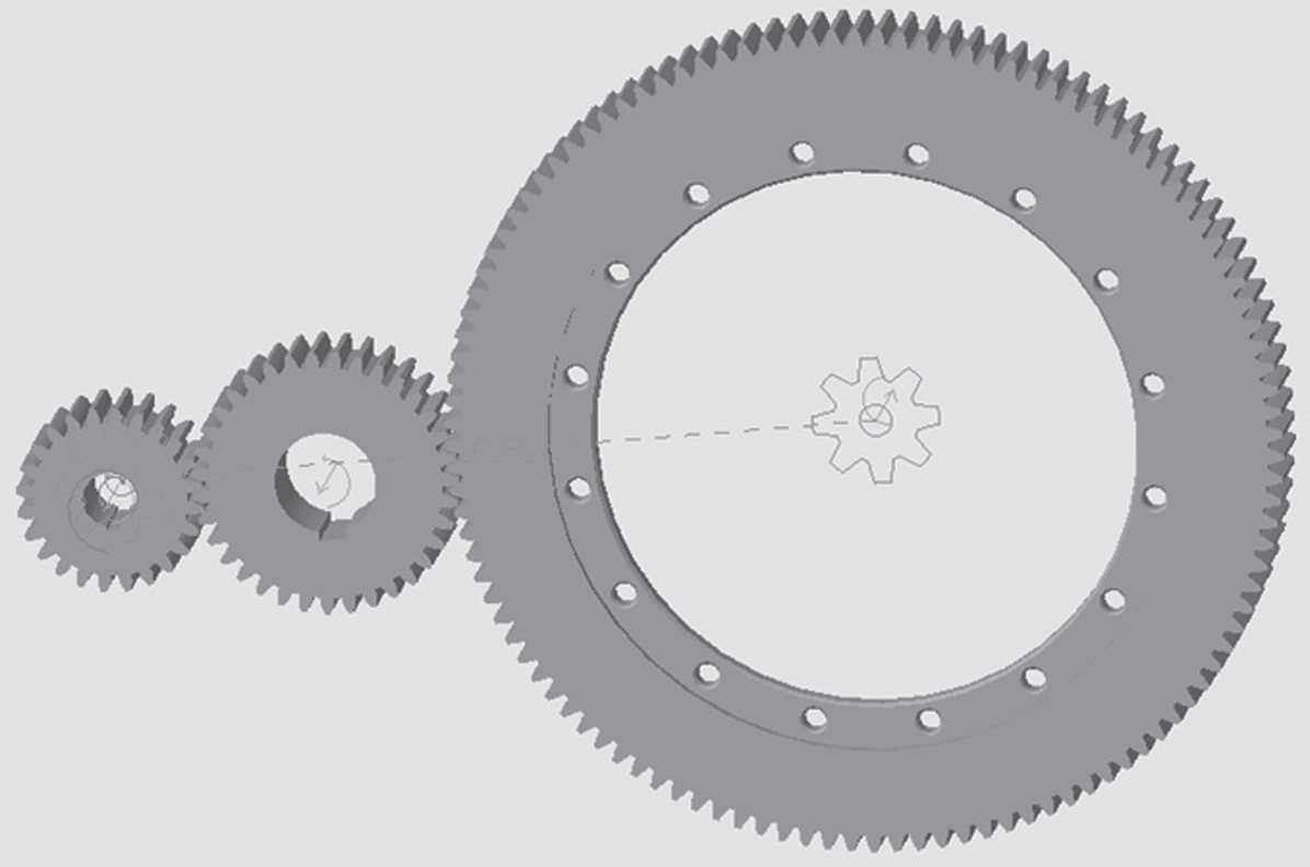
- Cutting Path Planning: Instead of single – tooth machining, which is prone to inconsistent tooth pitch due to tool wear, a “contour – parallel and constant – height” milling strategy is adopted. This involves milling in a circular motion around the gear mold and maintaining a constant cutting height during semi – finishing and finishing operations. Figure 1 shows this milling path clearly.
- Avoiding 余量堆积: To prevent the accumulation of machining allowance caused by tool wear, an alternating cutting direction is used. This ensures that the under – cutting caused by tool wear is evenly distributed rather than concentrated in one area.
- Pre – machining for Root Clearance: Before the constant – height milling, a root – clearance operation is carried out. As shown in Figure 2, this is because the cutting allowance at the rounded corners is relatively large, and tool deflection is more likely to occur. By performing root – clearance first, the subsequent milling process can be more stable.
- Optimizing Process Parameters: Reasonable planning of the machining process and setting of parameters such as cutting speed, feed rate, and machining allowance are essential for controlling tool wear and deflection. Instead of the traditional and costly trial – and – error method, finite – element simulation is employed to conduct cutting tests and study the impact of cutting parameters on tool wear.
| Milling Strategy | Description | Advantage |
|---|---|---|
| Contour – parallel and constant – height milling | Milling in a circular motion with a constant cutting height | Ensures consistent tooth pitch and surface finish |
| Alternating cutting direction | Changing the cutting direction alternately | Avoids allowance accumulation |
| Pre – machining for root – clearance | Machining the root area before main milling | Reduces tool deflection at rounded corners |
| Optimizing process parameters through simulation | Using finite – element simulation to set parameters | Cost – effective and accurate parameter selection |
3. Establishing the Finite – Element Milling Model
3.1 Material Parameters
DC53 mold steel has specific physical properties that need to be accurately defined in the finite – element model. Table 1 lists its key physical parameters, including elastic modulus, shear modulus, Poisson’s ratio, density, thermal expansion coefficient, and thermal conductivity. These parameters are crucial for accurately simulating the material’s behavior during milling.
| Physical Property | Value |
|---|---|
| Elastic Modulus (MPa) | 212660 |
| Shear Modulus (MPa) | 83104 |
| Poisson’s Ratio | 0.28 |
| Density (kg/m³) | 7870 |
| Thermal Expansion Coefficient (× 10⁻⁶/℃) | 13.5 |
| Thermal Conductivity (W/(m·K)) | 23.8602 |
3.2 Tool Wear Model
Among the commonly used wear models, the Usui model is selected for this study. Since metal cutting is a continuous process, the Usui model is more suitable. The formula for the Usui model is \(\omega=\int a P V e^{-b / T} d t\), where \(a = 1.0e^{-6}\), \(b = 850\) are experimental calibration coefficients, P is the contact pressure, V is the relative speed, T is the contact surface temperature, and t is the time increment. This model allows for a more accurate prediction of tool wear during the milling process.
3.3 Building the Cutting Model
To save simulation time, the workpiece is simplified into an inclined – plane model. Considering the angle range of the gear teeth (60° – 80°), an inclined – plane angle of 70° is chosen. A Zhuzhou Diamond HMX – 4B high – hardness four – flute straight – shank ball – nose end – mill with a helix angle of 35° is selected. To improve the simulation accuracy, local mesh refinement is performed on both the workpiece and the tool, as shown in Figure 3. The tool’s motion includes rotation around its axis and translation along the inclined plane, which is consistent with the “contour – parallel and constant – height” milling path.
4. Simulation Results Analysis
4.1 Design of Single – Factor Experiments
The main factors considered in this study are spindle speed, milling depth, and feed rate. A series of single – factor experiments are designed to observe their impacts on cutting force and tool wear. The milling process is set as semi – finishing and finishing, with relatively small milling depths. The cutting force is calculated using the root – mean – square method. Table 2 shows the details of the single – factor experiment design and results.
| Experiment Number | Spindle Speed (r/min) | Milling Depth (mm) | Feed Rate (mm/min) | Cutting Force \(F_x\) (N) | Tool Wear (mm) |
|---|---|---|---|---|---|
| 1 | 5000 | 0.05 | 1000 | 8.4885211 | 0.0000795 |
| 2 | 6000 | 0.05 | 1000 | 11.60356757 | 0.0000358 |
| 3 | 7000 | 0.05 | 1000 | 10.81251897 | 0.00000708 |
| 4 | 8000 | 0.05 | 1000 | 14.50086048 | 0.0000401 |
| 5 | 9000 | 0.05 | 1000 | 15.12411714 | 0.0000374 |
| 6 | 7000 | 0.01 | 1000 | 8.75018023 | 0 |
| 7 | 7000 | 0.025 | 1000 | 12.61733986 | 0.0000165 |
| 8 | 7000 | 0.1 | 1000 | 21.9879946 | 0.000173 |
| 9 | 7000 | 0.2 | 1000 | 43.07549081 | 0.000342 |
| 10 | 7000 | 0.05 | 600 | 11.80132335 | 0.000144 |
| 11 | 7000 | 0.05 | 700 | 10.66626074 | 0.0000873 |
| 12 | 7000 | 0.05 | 800 | 13.99749653 | 0 |
4.2 Impact of Cutting Parameters on Cutting Force
- Spindle Speed: As shown in Figure 4a, with the increase of spindle speed, the cutting force shows a slow – growing trend. In the semi – finishing and finishing processes with small milling depths, the impact of spindle speed on cutting force is relatively small.
- Milling Depth: Figure 4b indicates that when the milling depth is less than or equal to 0.05 mm, the cutting force changes slightly. However, when the milling depth exceeds 0.05 mm, the cutting force increases significantly with the increase of milling depth.
- Feed Rate: From Figure 4c, it can be seen that when the milling depth is 0.05 mm, within the experimental range, the impact of the feed rate on the cutting force is not significant.
4.3 Impact of Cutting Parameters on Tool Wear
- Spindle Speed: Figure 5a shows that within the experimental range, as the spindle speed increases, the tool wear first decreases and then increases.
- Milling Depth: When the milling depth is less than or equal to 0.05 mm, the tool wear changes little and the values are relatively small. When the milling depth is greater than 0.05 mm, the tool wear increases significantly with the increase of milling depth, which is consistent with the impact of milling depth on cutting force, as shown in Figure 5b.
- Feed Rate: In the case of a milling depth of 0.05 mm, when the feed rate is less than or equal to 800 mm/min, the tool wear increases as the feed rate decreases. When the feed rate is greater than 800 mm/min, the tool wear is relatively small and changes little, as depicted in Figure 5c.
4.4 Location of Tool Wear
Figure 6 shows the tool wear location. When milling DC53 mold steel with a high cutting speed and a small milling depth, both the rake face and the flank face of the tool are worn. The maximum tool wear position is around 70°. By establishing workpiece models with angles of 60° and 80° and conducting cutting simulations, it is found that the maximum tool wear positions are around 60° and 80° respectively. This indicates that the maximum tool wear is related to the tool – workpiece contact position.
5. Tool Selection and Effect in Actual Machining
5.1 Actual Machining Cutting Parameters
Before quenching, a rough – machining process is carried out, leaving 0.1 mm of machining allowance for subsequent operations. Based on the simulation results, when the milling depth is less than or equal to 0.05 mm, both the cutting force and tool wear are relatively small. Considering the actual machining time and effect, after quenching, a second rough – machining is performed, leaving 0.02 mm of machining allowance for semi – finishing and finishing. The semi – finishing allowance is set to 0.01 mm, and the finishing allowance is also 0.01 mm. The spindle speed is set to 7000 r/min, and the feed rate is set to 800 mm/min.
5.2 Tool Life Verification
To improve the first – pass machining accuracy and avoid frequent rework, a tool life verification is carried out for the semi – finishing process. When the remaining machining allowance after semi – finishing is less than 0.012 mm and the tool deflection is less than 0.005 mm, the semi – finishing of the tooth surface is considered to be in place. Table 3 shows the results of the tooth surface semi – finishing, and Figures 7 and 8 show the remaining machining allowance curve and tool wear respectively.
| Parameter | Part 1 | Part 2 | Part 3 | Part 4 |
|---|---|---|---|---|
| Tool Wear | 0.0011 | 0.0027 | 0.0034 | 0.0047 |
| Remaining Machining Allowance Before Semi – finishing | 0.018 – 0.027 | 0.019 – 0.031 | 0.015 – 0.03 | 0.018 – 0.03 |
| Remaining Machining Allowance After Semi – finishing | 0.0074 – 0.012 | 0.0043 – 0.012 | 0.0056 – 0.012 | 0.0039 – 0.016 |
| Tool Deflection | 0.002 | 0.0021 | 0.0006 – 0.002 | 0.011 |
It can be seen from the figures that the first three machining operations are in place, and the remaining tooth surface allowance after the fourth machining is not in place. This indicates that the tool for semi – finishing the contour – parallel tooth surface can be used at most three times. The maximum tool wear position is mainly concentrated around 70°, which is consistent with the simulation results and verifies the accuracy of the simulation.
5.3 Machining Results
A ZEISS coordinate measuring machine with a dedicated gear detection module is used to measure the gear mold. According to the DIN3965 standard, the measured gear mold reaches the 1 – level accuracy. The roughness detection result is \(R_a<0.26\ \mu m\), eliminating the need for subsequent polishing, and the mold can be directly used for product extrusion.
6. Conclusion
Through finite – element analysis and other methods, this study has optimized the milling process for automotive differential gear molds, effectively solving the problems of high material hardness, severe tool wear, and large tool deflection. The following conclusions can be drawn:
- For milling difficult – to – machine materials, the rational setting of cutting parameters is of utmost importance. The finite – element analysis method can provide a reliable basis for parameter selection.
- Among the cutting parameters in high – speed milling, the milling depth has the greatest impact on both the cutting force and tool wear. When the milling depth is small, the changes in cutting force and tool wear are minimal, and the values are relatively low. Once the milling depth reaches a certain value, an increase in milling depth leads to a significant increase in both cutting force and tool wear, and their trends are basically consistent.
- The main wear location of the ball – nose end – mill is the part that has more contact with the workpiece, which is related to the workpiece angle. When high – speed finishing DC53 mold steel, both the rake face and the flank face of the tool are subject to wear.
- When milling high – hardness materials, old tools can be used reasonably. The method proposed in this paper can provide a reference for determining the number of times a tool can be used.
In summary, this research provides valuable insights and practical solutions for the milling of gear cold extrusion molds, which can be extended to the machining of other difficult – to – machine materials in the manufacturing industry. Future research can focus on further optimizing the process parameters, exploring new tool materials, and improving the accuracy and efficiency of the milling process.