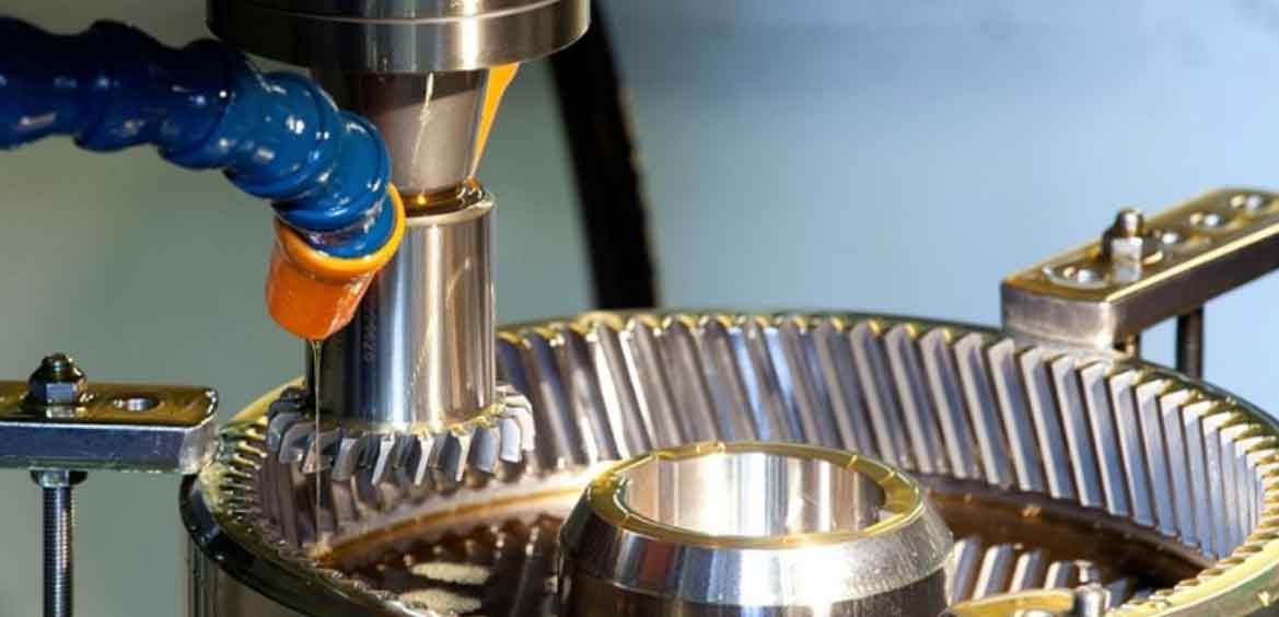
Non-circular gears enable variable transmission ratios while maintaining compact design and reliable power transmission. This research establishes a comprehensive framework for four-axis CNC gear shaping of non-circular gears, addressing mathematical modeling, kinematic analysis, error compensation, and experimental validation.
Mathematical Model and Process Design
The tooth profile generation follows the envelope principle where the cutter’s involute profile sweeps the target geometry through coordinated motion. The coordinate transformation between cutter and workpiece systems is expressed as:
$$ \mathbf{R} = \mathbf{M}^{01} \mathbf{M}^{12} \mathbf{r}_2 $$
where $\mathbf{M}^{01}$ and $\mathbf{M}^{12}$ represent homogeneous transformation matrices. For elliptical gears with transmission ratio $i_{12} = 1.0510 – 0.3234\cos\theta$ and center distance $a = 80mm$, the generated profile is shown below:

Key process parameters for gear shaping include:
| Parameter | Value |
|---|---|
| Module | 1.5 mm |
| Pressure Angle | 20° |
| Radial Depth of Cut | 3.375 mm |
| Circular Feed | 0.45 mm/stroke |
| Cutting Speed | 20 m/min |
Kinematic Modeling and Error Compensation
The four-axis gear shaping machine topology follows $WC_1YMXC_2ZD$ configuration. Forward kinematics are derived using homogeneous transformations:
$$ \begin{bmatrix} \mathbf{P}_W \\ \mathbf{V}_W \end{bmatrix} = \mathbf{F}_{TW}(X,Y,Z,C_1,C_2) \begin{bmatrix} \mathbf{P}_T \\ \mathbf{V}_T \end{bmatrix} $$
Geometric errors are modeled through differential motion matrices:
$$ \mathbf{E}_T^W = \begin{bmatrix} 1 & -\varepsilon_z & \varepsilon_y & \delta_x \\ \varepsilon_z & 1 & -\varepsilon_x & \delta_y \\ -\varepsilon_y & \varepsilon_x & 1 & \delta_z \\ 0 & 0 & 0 & 1 \end{bmatrix} $$
Error compensation utilizes the Jacobian-based decoupling:
$$ \mathbf{C}_T^W = (\mathbf{J}^T\mathbf{J})^{-1}\mathbf{J}^T\mathbf{E}_T^W $$
Automatic Programming and Simulation
The MATLAB-based system generates optimized NC code through computational modules:

G-code structure for four-axis gear shaping includes coordinated commands:
$$ \text{G01 X}x_i\text{ Y}y_i\text{ C1}\theta_i\text{ C2}\psi_i $$
VERICUT simulations validate toolpaths and error compensation effectiveness:
| Compensation | Max Error (mm) | Conformance Rate |
|---|---|---|
| Uncompensated | 0.141 | 92.46% |
| Compensated | 0.089 | 99.90% |
Experimental Validation
WF800S four-axis gear shaping machine processed elliptical gears ($z=53$, $e=0.1577$). 3D scanning revealed:

Critical quality metrics from gear shaping experiments:
| Analysis Type | Avg. Deviation (mm) | Std. Deviation (mm) |
|---|---|---|
| 3D Comparison | -0.0509~0.0514 | 0.0770 |
| 2D Profile | -0.0329~0.0207 | 0.0357 |
Conclusions and Future Work
Four-axis CNC gear shaping enables efficient non-circular gear production with 99.9% profile conformance within ±0.1mm tolerance. Future research will investigate thermal-error compensation and variable-parameter gear shaping optimization.
