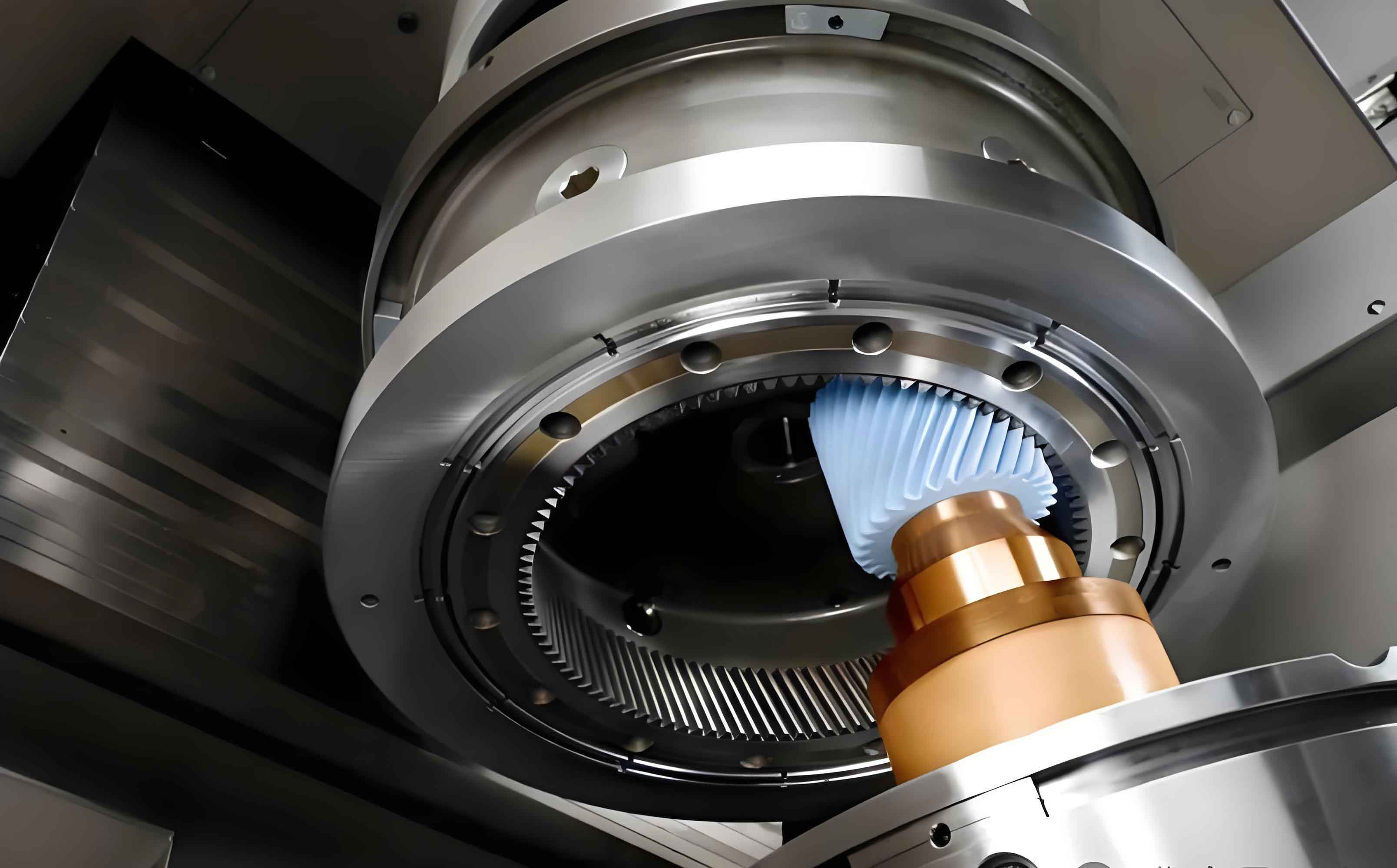
Internal gearing power honing is a critical finishing process for high-precision gears in new energy vehicles, offering superior noise reduction and eliminating surface burns. Traditional honing requires customized diamond dressing wheels for each modification profile, increasing costs and limiting flexibility. This study presents a novel multi-axis linkage approach enabling arbitrary topological modification using standard tools. The methodology integrates kinematic modeling, sensitivity analysis, and dynamic programming optimization to achieve flexible gear honing.
Fundamentals of Internal Gearing Power Honing

The kinematic relationship between honing wheel and workpiece during axial feed is governed by:
$$ \Delta C_2 = \frac{\tan \beta_d}{r_d} \cdot \Delta Z $$
$$ \omega_d = \frac{N_h}{N_d} \omega_h \pm \frac{2 \sin \beta_d}{m_n N_d} \cdot v_z $$
where \( \beta_d \) is workpiece helix angle, \( r_d \) is pitch radius, and \( m_n \) is normal module. Three honing processes are compared:
| Process | Efficiency | Precision | Wheel Utilization |
|---|---|---|---|
| Radial Feed | Highest | Lowest | Narrow |
| Intermittent Feed | Lowest | Highest | Wide |
| Continuous Feed | Moderate | Moderate | Wide |
The mathematical model for diamond dressing gear tooth surface is:
$$ \mathbf{r}_1 = \begin{bmatrix}
r_{b1} \cos(\sigma_0 + \theta + \lambda) + r_{b1} \lambda \sin(\sigma_0 + \theta + \lambda) \\
r_{b1} \sin(\sigma_0 + \theta + \lambda) – r_{b1} \lambda \cos(\sigma_0 + \theta + \lambda) \\
p \theta
\end{bmatrix} $$
Honing wheel surfaces are derived via spatial conjugate meshing theory, enabling precise gear honing simulation.
Workpiece Tooth Surface Modification
Topological modification combines profile and lead crowning. The crowned surface equation is:
$$ \mathbf{r}_{\text{mod}} = \begin{bmatrix}
r_b \cos(\sigma_0 + \theta + \lambda + \Delta\lambda) + r_b \lambda \sin(\cdot) + H_i \sin(\cdot) \\
r_b \sin(\sigma_0 + \theta + \lambda + \Delta\lambda) – r_b \lambda \cos(\cdot) – H_i \cos(\cdot) \\
p \theta
\end{bmatrix} $$
where \( H_i \) and \( \Delta\lambda \) are profile and lead crowning functions. Optimization targets transmission error (TE), contact stress (\( \sigma_c \)), and temperature (\( T_c \)):
$$ \text{minimize} \quad [\text{TE}_{\text{pp}}, \max(\sigma_c), \max(T_c)] $$
KISSsoft simulation for a 29/83 gear pair shows significant improvements after gear honing modification:
| Parameter | Unmodified | Modified | Reduction |
|---|---|---|---|
| TEpp (μm) | 0.85 | 0.60 | 29% |
| σc (MPa) | 2485 | 1415 | 43% |
| Tc (°C) | 176 | 115 | 35% |
Sensitivity Analysis of Modification Parameters
The sensitivity matrix relates axis motions to surface deviations:
$$ \mathbf{A} = \begin{bmatrix}
\frac{\partial \varepsilon_1}{\partial p_1} & \cdots & \frac{\partial \varepsilon_1}{\partial p_t} \\
\vdots & \ddots & \vdots \\
\frac{\partial \varepsilon_s}{\partial p_1} & \cdots & \frac{\partial \varepsilon_s}{\partial p_t}
\end{bmatrix} $$
Axis motions are parameterized as 5th-order polynomials:
$$ E_{wh}(L_Z) = E_0 + \sum_{k=0}^{5} a_k L_Z^k $$
$$ \phi_A(L_Z) = \phi_{A0} + \sum_{k=0}^{5} b_k L_Z^k $$
Sensitivity coefficients reveal:
- X-axis: Dominates lead direction modification
- A-axis: Controls profile direction modification
- B-axis: Causes detrimental diagonal distortions
Maximum normal deviations per parameter (μm):
| Parameter | Deviation | Parameter | Deviation |
|---|---|---|---|
| a0 | 173.4 | b0 | 111.1 |
| c0 | 267.3 | c5 | 102.4 |
Results justify excluding B-axis from gear honing modification strategies.
Multi-Axis Topological Modification
The dynamic programming model minimizes normal deviation:
$$ V_k(\mathbf{r}_k, u_k, \cdots) = \min \left\{ v_k(\mathbf{r}_k, u_k), V_{k+1}(\cdots) \right\} $$
$$ v_i(\mathbf{r}_i, u_i) = \sum_{j=1}^{45} \mathbf{n}_{ij} \cdot (\mathbf{r}_c – \mathbf{r}_{ij}) $$
Three case studies demonstrate the gear honing approach:
| Case | Gear Parameters | Max Crown (μm) | Avg Error (μm) | Iterations |
|---|---|---|---|---|
| 1 | z=39, β=22° | 24.2 | 3.05 | 11 |
| 2 | z=73, β=33° | 25.0 | 3.58 | 10 |
| 3 | z=73, β=33° | 24.2 | 4.23 | 13 |
Optimized axis motions generated through gear honing modification:
$$ \phi_w(\phi_h, L_z) = \frac{N_h}{N_d} \phi_h \pm \frac{2 \sin \beta_d}{m_n N_d} L_z $$
Error distribution analysis shows maximum deviations at tooth edges (4-5μm) versus centers (1-2μm), demonstrating effective multi-axis gear honing control.
Conclusion
This research establishes a comprehensive framework for flexible topological modification in internal gearing power honing. The integrated methodology combines kinematic modeling, sensitivity analysis, and dynamic programming optimization to enable arbitrary crown modifications using standard honing wheels. Experimental validation shows 3-5μm surface accuracy across varying gear geometries, achieving 29-43% reductions in transmission error and contact stress. Future work will implement real-time compensation for manufacturing variations during gear honing processes.
