
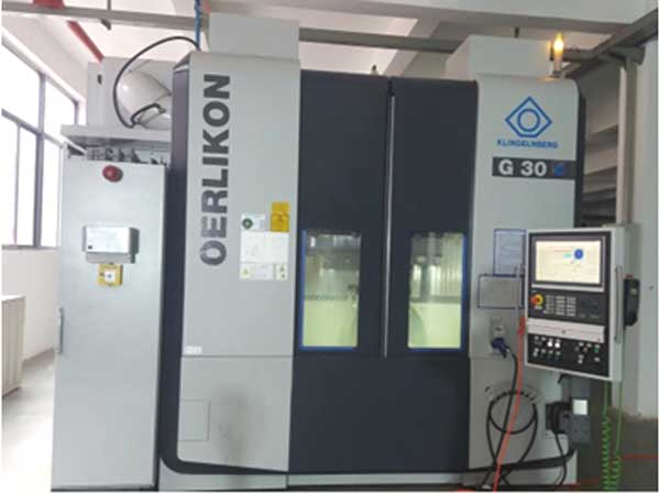
With the rapid development of domestic automotive products, the manufacturing importance of spiral bevel gears has significantly increased, demanding higher-precision CNC machining equipment. The spiral bevel gear milling machine is the most critical component in high-efficiency precision machining systems for automotive spiral bevel gears. Its dynamic performance directly affects subsequent processes, operational efficiency, and product quality. To address this, we developed a signal acquisition and testing system to perform dynamic tests on the machine structure. Using test results, we refined the boundary conditions of the finite element model to achieve high-fidelity simulations. Through sensitivity analysis and optimization, we enhanced the machine’s first-order natural frequency by 46.8% while reducing mass by 2.1%, significantly improving dynamic performance in gear milling applications.
1. Dynamic Testing Methodology
We evaluated the dynamic characteristics of the spiral bevel gear milling machine using impact hammer excitation and accelerometers. The vibration response was processed through our proprietary SD150 signal analysis system. The machine structure comprises three major assemblies: bed, column (including tool holder), and workpiece box (including ram and workpiece spindle), forming five motion axes (X, Y, Z, A, B).
The governing equation for the N-degree-of-freedom linear elastic system is:
$$ [M]\{\ddot{x}\} + [C]\{\dot{x}\} + [K]\{x\} = \{f(t)\} \tag{1} $$
where $[M]$, $[C]$, and $[K]$ are mass, damping, and stiffness matrices. Applying Fourier transform:
$$ (-\omega^2[M] + j\omega[C] + [K])\{X(\omega)\} = \{F(\omega)\} \tag{2} $$
The frequency response function (FRF) matrix is derived as:
$$ [H(\omega)] = (-\omega^2[M] + j\omega[C] + [K])^{-1} \tag{3} $$
For excitation at point p and response measurement at point l:
$$ H_{lp}(\omega) = \sum_{r=1}^{N} \frac{\phi_{lr}\phi_{pr}}{-\omega^2 m_r + j\omega c_r + k_r} \tag{4} $$
Modal parameters extracted from FRF data are summarized below:
| Mode | Frequency (Hz) | Mode Shape Description |
|---|---|---|
| 1 | 28.921 | Rocking along Y-direction |
| 2 | 65.334 | Torsional vibration about Z-axis |
| 3 | 77.893 | Column rocking about X-axis |
| 4 | 94.576 | Column rocking about Y-axis with bed vibration |
| 5 | 147.964 | Second-order Z-direction bed vibration (workpiece box) |
| 6 | 158.367 | Column vibration along Z-axis |
| 7 | 174.689 | Second-order Z-direction bed vibration (column) |
2. Finite Element Modeling and Validation
A high-fidelity FE model was developed using SolidWorks Simulation. Material properties and boundary conditions were calibrated against test data. The modal analysis results show excellent correlation with experimental measurements (max error = 4.12%):
| Mode | Simulated Frequency (Hz) | Mode Shape Description |
|---|---|---|
| 1 | 27.322 | Rocking along Y-direction |
| 2 | 62.379 | Torsional vibration about Z-axis |
| 3 | 79.559 | Column rocking about X-axis |
| 4 | 94.212 | Column rocking about Y-axis with bed vibration |
| 5 | 155.264 | Second-order Z-direction bed vibration |
| 6 | 179.204 | Second-order Z-direction bed vibration |
3. Sensitivity Analysis for Gear Milling Dynamics
The sensitivity of natural frequency $\omega_i$ to design parameter $b_j$ is calculated as:
$$ \frac{\partial \omega_i}{\partial b_j} = \frac{1}{2\omega_i} \frac{\partial}{\partial b_j} \left( \frac{\{\phi_i\}^T [K] \{\phi_i\}}{\{\phi_i\}^T [M] \{\phi_i\}} \right) \tag{5} $$
Expanding the derivative:
$$ \frac{\partial \omega_i}{\partial b_j} = \frac{1}{2\omega_i} \left[ \frac{ \{\phi_i\}^T \frac{\partial [K]}{\partial b_j} \{\phi_i\} – \omega_i^2 \{\phi_i\}^T \frac{\partial [M]}{\partial b_j} \{\phi_i\} }{ \{\phi_i\}^T [M] \{\phi_i\} } \right] \tag{6} $$
Sensitivity coefficients for critical design variables are:
| Design Variable | Initial Value | Bending Sensitivity | Torsion Sensitivity |
|---|---|---|---|
| Column backplate angle | 162° | 65,230 | 34,251 |
| Column rib transition radius | 200 mm | 55,240 | 28,650 |
| Column height | 3,000 mm | 58,770 | 39,248 |
| Toolbox length | 1,500 mm | 4,716 | 3,635 |
| Base height | 1,000 mm | 17,589 | 12,360 |
| Base width | 4,400 mm | 7,984 | 5,258 |
| Base length | 5,800 mm | 10,250 | 4,658 |
4. Optimization of Gear Milling Machine
We formulated the optimization problem as:
$$ \text{Minimize: } M_{\text{total}} = \sum \rho_i V_i \tag{7} $$
$$ \text{Subject to: } \omega_1 \geq 20 \text{ Hz} \tag{8} $$
where $\omega_1$ is the first natural frequency to avoid resonance during gear milling (maximum operating frequency = 20 Hz). High-sensitivity variables were selected for optimization. After 14 iterations, convergence was achieved with significant improvements:
| Parameter | Initial | Optimized | Improvement |
|---|---|---|---|
| Column backplate angle | 162° | 154° | – |
| Column rib radius | 200 mm | 250 mm | – |
| Column height | 3,000 mm | 2,600 mm | – |
| Base height | 1,000 mm | 800 mm | – |
| Total mass | 21,484 kg | 21,030 kg | -2.1% |
| 1st natural frequency | 28.322 Hz | 41.572 Hz | +46.8% |
| Y-rocking amplitude | 0.26 mm | 0.21 mm | -19.2% |
| Z-torsion amplitude | 0.23 mm | 0.18 mm | -21.7% |
These modifications improved the overall dynamic performance of the spiral bevel gear milling machine by 19% while reducing material consumption by 454 kg. The methodology has been successfully applied to similar machinery, yielding annual savings exceeding $500,000 in design and testing costs.
5. Conclusion
Integrating dynamic testing, FE simulation, and sensitivity analysis provides a scientific approach to optimize spiral bevel gear milling machines. Validated FE models accurately predict dynamic behavior, while sensitivity analysis identifies critical design variables. Our optimization methodology simultaneously increases fundamental natural frequencies by 46.8% and reduces mass by 2.1%, significantly enhancing machining precision and structural longevity in gear milling operations. This approach demonstrates substantial economic benefits and is transferable to other precision machine tools requiring dynamic performance enhancement.