
Transmission Error (TE) is a critical performance parameter for evaluating the accuracy of gear transmission systems, serving as a primary excitation source for vibration and noise. While extensive research has focused on TE in single gear pairs, studies on gear transmission chains, particularly planetary gear systems, remain limited. This paper analyzes the sources and characteristics of TE in planetary gear systems, emphasizing factors influencing transmission accuracy and key aspects for ensuring high motion precision in reducers. By examining error components and their propagation, we aim to support the design and manufacturing of low-vibration, high-precision planetary gear drives.
In planetary gear systems, transmission errors arise from various factors, including manufacturing inaccuracies, tooth modifications, load-induced deformations, shaft deflections, assembly misalignments, and bearing inaccuracies. Understanding these elements is essential for optimizing the performance of planet gears in applications such as robotics and precision machinery.
Factors Influencing Transmission Error in Planetary Gears
The transmission error in planetary gears can be attributed to several key components, each contributing uniquely to the overall system behavior. The primary factors include cumulative pitch error, single pitch error, tooth profile error, load-dependent deformations, eccentricities, and bearing inaccuracies. These errors manifest as periodic and random variations, affecting both motion accuracy and dynamic response.
Cumulative pitch error (Fp) results from manufacturing imperfections like installation eccentricity, tool wear, and machine tool inaccuracies. It typically exhibits a sinusoidal pattern superimposed with random variations. For a gear with angular position φ, this error can be approximated as:
$$ \delta_p = F_p \cos(\varphi + \varphi_0) $$
Single pitch error (fpt) arises from tool inaccuracies and machining vibrations, appearing as random fluctuations over the cumulative error. Although small in magnitude compared to Fp, it contributes to high-frequency noise in planet gears.
Tooth profile error (ffα) and intentional profile modifications, such as tip and root relief, are designed to compensate for load-induced deflections and stiffness variations. These errors repeat Z times per revolution (where Z is the number of teeth) and can be expressed using a Fourier series:
$$ \delta_f = \sum_{i=1}^{5} \delta_{Ti} \cos[iZ(\varphi + \varphi_{Ti0})] $$
Load-dependent deformation (δa) includes bending and contact deformations under operational loads. It is proportional to the applied load and exhibits periodic behavior at tooth mesh frequency and its harmonics. This component is a primary focus in gear design software for TE analysis.
Eccentricity errors (e) due to assembly misalignments or shaft deflections introduce low-frequency periodic variations. The resulting error is given by:
$$ \delta_e = e \tan(\alpha_t) \cos(\varphi + \varphi_{e0}) $$
Bearing inaccuracies contribute additional periodic errors, though their exact form depends on bearing precision and are challenging to model simply.
The relative magnitudes of these errors are summarized in Table 1, based on typical values for gears with diameter d=100 mm, module m=2–3.5 mm, face width B=30 mm, and ISO grade 5 accuracy.
| Error Type | Fp | fpt | ffα | fHβ | e tan(αt) | δa |
|---|---|---|---|---|---|---|
| Error (μm) | 19 | 6 | 6 | 8.5 | 4–10 | 1–6 |
Cumulative pitch error and eccentricity are the dominant contributors, being 3–4 times larger than other errors. Thus, they critically influence the motion accuracy of planet gears. Combining these, the total error for a single gear can be approximated as:
$$ \delta_Z = \delta_A \cos(\varphi + \varphi_{0A}) + \sum_{i=1}^{5} \delta_{Ti} \cos[iZ(\varphi + \varphi_{0Ti})] $$
Here, the first term represents shaft-frequency errors (low frequency, high amplitude), and the second term represents tooth-frequency errors (high frequency, lower amplitude). This distinction is vital for analyzing planetary gear systems, where multiple planet gears interact.
Transmission Error in Single Gear Pairs
For a single pair of gears (e.g., driving gear Z1 and driven gear Z2), the transmission error referenced to the output shaft (Z2) is derived from the individual errors of both gears. The gear ratio is u12 = Z2/Z1, and angular positions relate as φ1 = u12 φ2. The TE is expressed as:
$$ TE_{12} = \frac{\delta_{Z1} + \delta_{Z2}}{r_{b2}} = \frac{1}{r_{b2}} \left[ \delta_{A1} \cos(\omega_1 t + \varphi_{0A1}) + \delta_{A2} \cos(\omega_2 t + \varphi_{0A2}) + \sum_{i=1}^{5} \delta_{T1i} \cos(i Z_1 \omega_1 t + \varphi_{0T1i}) + \sum_{i=1}^{5} \delta_{T2i} \cos(i Z_2 \omega_2 t + \varphi_{0T2i}) \right] $$
where rb2 is the base radius of gear Z2, and ω1, ω2 are angular velocities. The shaft-frequency components (ω1, ω2) differ by the gear ratio u12, while tooth-frequency components (Z1ω1 = Z2ω2) are identical. Shaft-frequency errors dominate transmission accuracy due to their higher amplitudes, whereas tooth-frequency errors, though smaller, generate significant vibration accelerations due to their higher frequencies (Z2 times the shaft frequency). This is particularly relevant in planet gears, where mesh frequencies can be high.
Transmission Error in Fixed-Axis Gear Chains
In multi-stage fixed-axis gear systems (with k pairs of gears Z1j, Z2j for j=1 to k), the cumulative TE referenced to the final output shaft Z2k involves summing contributions from all pairs, scaled by the speed ratios from each stage to the reference shaft. The overall TE is:
$$ TE_{1k} = \sum_{j=1}^{k} TE_{12jk} = \sum_{j=1}^{k} \left\{ \frac{1}{r_{b2j} u_{jk}} \left[ \delta_{A1j} \cos(\omega_{1j} t + \varphi_{0A1}) + \delta_{A2j} \cos(\omega_{2j} t + \varphi_{0A2j}) + \sum_{i=1}^{5} \delta_{T1ji} \cos(i Z_{1j} \omega_{1j} t + \varphi_{0T1ji}) + \sum_{i=1}^{5} \delta_{T2ji} \cos(i Z_{2j} \omega_{2j} t + \varphi_{0T2ji}) \right] \right\} $$
Here, ujk = Π u12j (from j+1 to k) is the speed ratio from stage j to the output. Each error component retains its original frequency but is amplitude-scaled by 1/ujk. Thus, the spectrum includes all shaft and tooth frequencies from all stages, with lower-amplitude contributions from earlier stages due to ratio scaling. For planet gears in such chains, this scaling affects how errors propagate through the system.
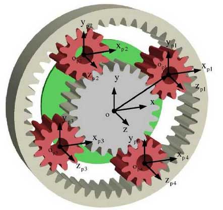
Transmission Error in Planetary Gear Systems
Planetary gear systems, such as epicyclic or star arrangements, involve multiple planet gears rotating around a central sun gear, with a ring gear and carrier. The TE analysis must account for relative motions between components. For a general planetary system with planet gears, the TE referenced to an output member (e.g., carrier) considers the relative angular velocities between meshing gears.
For each gear pair in the planetary system, the TE is computed relative to the carrier (planet gear frame). For a pair j, the error referenced to the output shaft k is:
$$ TE_{1k} = \sum_{j=1}^{k} TE_{12jk} = \sum_{j=1}^{k} \left\{ \frac{1}{r_{b2j} u_{jk}} \left[ \delta_{A1j} \cos(\omega_{1j}^{Hj} t + \varphi_{0A1}) + \delta_{A2j} \cos(\omega_{2j}^{Hj} t + \varphi_{0A2j}) + \sum_{i=1}^{5} \delta_{T1ji} \cos(i Z_{1j} \omega_{1j}^{Hj} t + \varphi_{0T1ji}) + \sum_{i=1}^{5} \delta_{T2ji} \cos(i Z_{2j} \omega_{2j}^{Hj} t + \varphi_{0T2ji}) \right] \right\} $$
where ω1j^{Hj}, ω2j^{Hj} are the relative angular velocities of gears Z1j and Z2j with respect to their carrier Hj, and ujk is the absolute speed ratio to the reference shaft. In planetary systems with n planet gears, the combined TE may average due to phase differences, reducing individual error amplitudes by approximately 1/√n. However, new frequency components at n times the mesh frequency may emerge.
For a K-H-V type planetary system (e.g., cycloidal or involute with small tooth difference), where the carrier H drives the output through a gear pair (Z1, Z2) with fixed ring gear, the TE referenced to gear Z1 is derived as follows. The speed ratio is ωH/ω1 = -Z1/(Z2 – Z1), and relative velocities are ω1^H = ω1 – ωH and ω2^H = ω2 – ωH. The TE becomes:
$$ TE_{H1} = \frac{1}{r_{b1}} \left[ \delta_{A1} \cos(\omega_1^H t + \varphi_{0A1}) + \delta_{A2} \cos(\omega_2^H t + \varphi_{0A2}) + \sum_{i=1}^{5} \delta_{T1i} \cos(i Z_1 \omega_1^H t + \varphi_{0T1i}) + \sum_{i=1}^{5} \delta_{T2i} \cos(i Z_2 \omega_2^H t + \varphi_{0T2i}) \right] $$
For example, with Z1=39, Z2=40, shaft-frequency errors appear at 40ω1 and 39ω1 on the output, while tooth-frequency errors are at 1560ω1. The high amplitude of shaft-frequency errors underscores the importance of controlling cumulative pitch and eccentricity errors in planet gears for precision applications.
Case Study: Planetary Cycloidal Reducer Transmission Error
Planetary cycloidal reducers, commonly used in robotics, combine a primary involute gear stage (Z1, Z2) with a secondary cycloidal stage (Z3, Z4). The input is typically at Z1, and the output at the carrier H. The overall TE referenced to H is the sum of errors from both stages, considering their relative kinematics.
The total TE is given by:
$$ TE_{1H} = \frac{1}{r_{b2} u_{2H}} \left[ \delta_{A1} \cos(\omega_1^H t + \varphi_{0A1}) + \delta_{A2} \cos(\omega_2^H t + \varphi_{0A2}) + \sum_{i=1}^{5} \delta_{T1i} \cos(i Z_1 \omega_1^H t + \varphi_{0T1i}) + \sum_{i=1}^{5} \delta_{T2i} \cos(i Z_2 \omega_2^H t + \varphi_{0T2i}) \right] + \frac{1}{r_3 u_{3H}} \left[ \delta_{A3} \cos(\omega_3^Q t + \varphi_{0A3}) + \delta_{A4} \cos(\omega_4^Q t + \varphi_{0A4}) + \sum_{i=1}^{5} \delta_{T3i} \cos(i Z_3 \omega_3^Q t + \varphi_{0T3i}) + \sum_{i=1}^{5} \delta_{T4i} \cos(i Z_4 \omega_4^Q t + \varphi_{0T4i}) \right] $$
where the speed ratios and relative velocities are:
$$ \omega_1^H = \omega_H \frac{Z_4 Z_2}{Z_1}, \quad \omega_2^H = -Z_4 \omega_H, \quad \omega_3^Q = Z_4 \omega_H, \quad \omega_4^Q = Z_3 \omega_H $$
$$ u_{2H} = \frac{\omega_2}{\omega_H} = -Z_3, \quad u_{3H} = \frac{\omega_3}{\omega_H} = 1, \quad i_{1H} = \frac{\omega_1}{\omega_H} = 1 + \frac{Z_4 Z_2}{Z_1} $$
Key observations for a reducer with i1H=121, Z4=40, Z3=39, Z1=20, Z2=60 include:
- Shaft-frequency errors from Z1 and Z2 appear at orders 39 and 40 on the output, with amplitudes reduced by Z3=39, making them minor contributors.
- Shaft-frequency errors from Z3 and Z4 (orders 40 and 39) have direct, unscaled impact on TE, dominating the overall error.
- Tooth-frequency errors from all gears are high (orders 2400 and 1560) but amplitude-scaled, reducing their significance for accuracy.
Experimental TE measurements for such reducers show prominent peaks at orders 39, 40, and 120 (second harmonic), confirming the dominance of cycloidal stage errors. Thus, minimizing cumulative pitch error and eccentricity in the cycloidal gears and ensuring precise bearing and carrier alignment are critical for high accuracy in planet gears.
Conclusion
Transmission error in planetary gear systems is primarily influenced by shaft-frequency and tooth-frequency components. Shaft-frequency errors, with higher amplitudes and lower frequencies, are crucial for transmission accuracy, while tooth-frequency errors, though smaller, drive vibration and noise. In fixed-axis and planetary gear chains, error amplitudes scale with speed ratios, but frequencies remain unchanged. For planetary systems, relative motions between components must be considered in TE analysis. In planetary cycloidal reducers, the final stage’s shaft-frequency errors (e.g., from cumulative pitch and eccentricity) are the main accuracy determinants. Thus, precision manufacturing and assembly of planet gears, focusing on reducing Fp and e, are essential for achieving high motion precision in applications such as robotics and precision drives.
Future work should explore advanced error compensation techniques and real-time monitoring for planetary gear systems to further enhance performance and reliability.